I don't want to get into a argument about this; but the point was the circuit may not work and having the option to add compensation would then allow you to get it working.
If you have a circuit that is an oscillator because of some unexpected characteristic of the load cable or crossover then the option to add a component even if it has to be derived by trial and error is surely a better option.
If the design was proposed as for a single application with a single defined load then that would be one thing but before getting into group buys the design should be adaptable enough to be made to work in most situations.
A ouput zobel and inductor would almost certainly be enough to achieve this, I mentioned the compensation only for extreem examples (which is partly why I didn't fully expand on how that should be achieved and partly because I just didn't think it through, should have know better there is always someone to pick you up on a sloppy point)
Regards,
Andrew
bridged please
In practice, its quite difficult to trigger the protection scheme on the LM1875. And, it isn't the screechy spike system either.
The LM1875 can do 4 ampers; however, if it is set up in the efficient ways you have mentioned, then. . . If/when one doesn't bump into the 4 amper limiter, then the transients are good for 12 ampers.
In practice, the actual limit is heat. Using two chips seems like a great solution, because it spreads the heat out of the way.
The part that I really like is that the chips will be operating at half gain. Therein is a lot of potential. Personally, that's ever so much more sensible than using two amplifiers in series (as with buffers and active pre).
So, I'm saying that this bridged LM1875 has every reason to succeed with only a passive preamp. I'd like to give the precedent of the miniature BTL Tripaths as an example.
The LM1875's, if bridged, will also be operating on a slightly lower voltage. I don't know about that one.
Personally, I find the prospect of a bridged LM1875 to be very exciting, unlike yet another pcb for just one chip. There's already so many of those.
AndrewT said:Hi Daniel,
adopting bridged for a chipamp does not automatically give [more generous power output]
All Chipamps are severely limited by their peak current ability.
Going to bridged asks each chipamp to supply double the current into your selected load.
This is more likely to trigger the protection mechanisms or at least sound wrong because the combination of chipamp + PSU is stressed more highly.
In practice, its quite difficult to trigger the protection scheme on the LM1875. And, it isn't the screechy spike system either.
The LM1875 can do 4 ampers; however, if it is set up in the efficient ways you have mentioned, then. . . If/when one doesn't bump into the 4 amper limiter, then the transients are good for 12 ampers.
In practice, the actual limit is heat. Using two chips seems like a great solution, because it spreads the heat out of the way.
The part that I really like is that the chips will be operating at half gain. Therein is a lot of potential. Personally, that's ever so much more sensible than using two amplifiers in series (as with buffers and active pre).
So, I'm saying that this bridged LM1875 has every reason to succeed with only a passive preamp. I'd like to give the precedent of the miniature BTL Tripaths as an example.
The LM1875's, if bridged, will also be operating on a slightly lower voltage. I don't know about that one.
Personally, I find the prospect of a bridged LM1875 to be very exciting, unlike yet another pcb for just one chip. There's already so many of those.
Hi Daniel,
do the numbers.
50W into 4r0 needs 20Vk and 5Apk. That's about the same amp set up as 27W into 8r0, requiring only 2.6Apk.
A bridged pair will do 100W into 8r0 needing 40Vpk and 5Apk.
Now attach a real speaker. 100W into 8ohms.
The transient peak current can be as high as 14Apk.
Those numbers apply to a 27W into 8r0 amp, with it's very much reduced supply voltage.
If one chooses to start with a 60W into 8ohm chipamp you don't have any hope of getting the amp to perform well in bridged mode, because the peak current requirement jumps to around 21Apk.
Don't be silly, just think about it and if need be, do more background reading.
AndrewT said:Hi Daniel,
do the numbers.
50W into 4r0 needs 20Vk and 5Apk. That's about the same amp set up as 27W into 8r0, requiring only 2.6Apk.
A bridged pair will do 100W into 8r0 needing 40Vpk and 5Apk.
Now attach a real speaker. 100W into 8ohms.
The transient peak current can be as high as 14Apk.
Those numbers apply to a 27W into 8r0 amp, with it's very much reduced supply voltage.
If one chooses to start with a 60W into 8ohm chipamp you don't have any hope of getting the amp to perform well in bridged mode, because the peak current requirement jumps to around 21Apk.
Don't be silly, just think about it and if need be, do more background reading.
I'm so glad to hear this news. Yes. Please disregard everything that I said about bridge application for this chip. Its apparently unviable, nonworking and inadvisable. So, I sincerely hope that nobody makes a bridge LM1875.
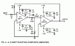
On bridging for the LM1875.
I can think of 3 reasons why one might wish to bridge this amp, and they have little to do with liberating maximum power, if that is what one want then it would be best to go for another chip.
Reason 1: You have a limited voltage power supply to play with like for example 12Volts, all Nat Semi chips produce around 6 watts on such a supply.....well in fact according to the Nat Semi data the LM1875 actually produces more than the other chips at that voltage, including the 3886.
Reason 2 In my experience the LM1875 actually sound sweetest running on 12 volts, many folk who have tried it say much the same, but maybe you need more power than 6 watts. Bridge application will of course do this, though you will only end up with around 24W equavilent to the std LM1875 trafo set-up.
Reason 3 You want the best sonic performance and that means (in my experience again) you need to run either SLA or SMPS power supply, to do this you need to run either 12V, 15V (using SMPS which is actually hard to locate at this voltage) or 24V (4 batteries) or SMPS. Having tested all of these except 15v the 12V sounds better in either config. Trafo set-ups to my ears are either grainy sounding and/or dull in the mids/highs.
So bridged application is probably not as daft as it might seem, and it is worth noting that the LM1876 is actually designed to be used in such a way, and of course the LM1876 is basically just a pair of 1875s in one package with a few small changes.
Bridging from my investigations can bring many benefits (power supply issues being covered), it appears that the only real deficit is that it will not improve cross-over distortion, which could in fact be a little worse. However I must say if power is all you want then there are probably far better options to be had with other chips, the thing is up till now most folk have only considered bridging on the grounds of power liberation. Anyhow I am interested enough in the idea to try it and will do so in the next few weeks, if it doesn't cut the sonic mustard it won't have cost me much to find out.
Re: Question for BWRX
It would make much more sense to use the LME49810 or one of its siblings to drive a FET output stage, even though it's roughly twice the price of the LM1875.
danielwritesbac said:Is it possible to use the little LM1875 to drive a FET output, and at the other end, also have a buffer input?
It would make much more sense to use the LME49810 or one of its siblings to drive a FET output stage, even though it's roughly twice the price of the LM1875.
Re: Re: Question for BWRX
Hey, it looks like your mini project really is the best option. Have you made one? I sure would like to see what it sounds like.
BWRX said:It would make much more sense to use the LME49810 or one of its siblings to drive a FET output stage, even though it's roughly twice the price of the LM1875.
Hey, it looks like your mini project really is the best option. Have you made one? I sure would like to see what it sounds like.

Bob_Sled said:I bet you're audible in the bathroom!
Indeed I was
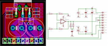
but that's off topic...In terms of the design, I've decided to try two different layouts - a basic and a full version. The basic version is just the basic components and fits on a 1"x1" pcb. A picture of the basic version schematic and layout are attached.
Attachments
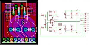
The full version includes options for components suggested by others and fits on a slightly larger 1.15"x1" pcb. A picture of the full version schematic and layout are attached.
I'll be putting both layouts on one board and have them made using expresspcb's miniboard service, which is three 3.8"x2.5" boards, no silkscreen or soldermask, for $59.90 shipped (very fast turn around too). If anyone knows of a better place to have these proto boards made feel free to let me know Two basic and two full layouts plus another little layout will fit on each board. These will just be used for testing the design.
I'll be putting both layouts on one board and have them made using expresspcb's miniboard service, which is three 3.8"x2.5" boards, no silkscreen or soldermask, for $59.90 shipped (very fast turn around too). If anyone knows of a better place to have these proto boards made feel free to let me know
Two basic and two full layouts plus another little layout will fit on each board. These will just be used for testing the design.Attachments
defect9 said:Do I smell a group buy in the future?
It's possible, but right now I'm drained from the Jordan JX92S group buy (which is close to being finished!).
renfrow said:sureelectronics, the chinese company selling cheap class-d boards is offering pcb prototyping, look for them as a seller or, try this link.
They're dirt cheap all right! Quality may be a bit iffy but a lot of people have bought the class d amps from them... I've used other Chinese board houses and had good results but I'll probably stick with expresspcb for the first set of prototype boards. They have good quality and the turn around time is very fast for the price - mainly because there's no soldermask or silkscreen but you don't need that for proving out a design.
Hey Brian,
I typically use Advanced Circuits $33 deal , but they require you to buy 4 (unless you get the student discount, in which you can order only one, but I am guessing you don't exactly qualify for that). Thus, I don't really think they would be a good fit for this project, but for something a little larger, the $33 price is good for any board up to 60 square inches. The prototype boards are full spec (1oz. copper, top and bottom mask/silk), and are VERY nice.
I typically use Advanced Circuits $33 deal , but they require you to buy 4 (unless you get the student discount, in which you can order only one, but I am guessing you don't exactly qualify for that). Thus, I don't really think they would be a good fit for this project, but for something a little larger, the $33 price is good for any board up to 60 square inches. The prototype boards are full spec (1oz. copper, top and bottom mask/silk), and are VERY nice.
- Status
- This old topic is closed. If you want to reopen this topic, contact a moderator using the "Report Post" button.
- Home
- Amplifiers
- Chip Amps
- Mini LM1875 design