I think it's a variety of faults. When I first got my Z-5500 (used set from a friend) the pod wasn't working. The problem turned out to be corrosion on the board, cleaned it up and it worked well for about 2 months. Then died completely. No clue why. I got a replacement pod mostly for parts to build the bypass but I was able to fix this second pod, missing solder joint and broken capacitor. Other pods seem to have a logic failure. They all run very hot, so that's at least a contributing factor.
I would also like to know exactly why these units die, but Logitech has never released that information. If anyone here has any idea, please post?
Rick
I would also like to know exactly why these units die, but Logitech has never released that information. If anyone here has any idea, please post?
Rick
When I opened my sub box to make this last modification I thought the solder point on the lower part of the board looked a bit tight to me, so I did some tracing and found that point goes through the board and then comes back out and continues on up to the top of the board and terminates at WA126. This is a much easier (and safer) place to solder.The only thing I didn't manage to get working without a workaround was the center channel. So I still had to connect +8V to center enable on the subwoofer board
Thanks again Neuweiler for a great post.
Rick
Hi everybody!
I have bought z 5500 sub without control pod, the pid number of my sub is r608, can i build pod bypass like in this schematic http://www.dodaj.rs/f/2/Ba/1U3TDzV7/unnamed-2.jpg put everything in one plastic box and hook it with my sub with regular d-sub15 (VGA) cable? Thanks, Edge.
I have bought z 5500 sub without control pod, the pid number of my sub is r608, can i build pod bypass like in this schematic http://www.dodaj.rs/f/2/Ba/1U3TDzV7/unnamed-2.jpg put everything in one plastic box and hook it with my sub with regular d-sub15 (VGA) cable? Thanks, Edge.
Yes Edge, you should be able to build the pid bypass into a single project box. Look at post #518. You should be able to build that into a single project box like I did. I think for the higher PID numbers you can ignore the bit about the Center Channel power. Newer PIDs shouldn't need that. Also, you may want to buy a non-working pod (on eBay) just to get the proper VGA cable.
Good luck,
Rick
Good luck,
Rick
Yes Edge, you should be able to build the pid bypass into a single project box. Look at post #518. You should be able to build that into a single project box like I did. I think for the higher PID numbers you can ignore the bit about the Center Channel power. Newer PIDs shouldn't need that. Also, you may want to buy a non-working pod (on eBay) just to get the proper VGA cable.
Good luck,
Rick
Thanks Rick, I have started making my controller and next I will make my custom VGA cable. Just I didn't find any thread/topic about adding standby button, is there a way to do that? All the Best, Edge.
Hi all,
I just took home a Z5500 sub from the dump, for free so I have to try to get it to work")
The fuse is blown, opened her up and didn't spot anything wrong on the inside, didn't smell burned or anything. Unfortunately there where no speakers or the controller, so I have to fix my DIY bypass.
I found some schematics, but can figure out which one I need.
the PID is R740, but generally they speak about "636 or later" or "post 636".
Can I assume I have a 636 or later and that I can use the schematic in this post?
I just took home a Z5500 sub from the dump, for free so I have to try to get it to work
The fuse is blown, opened her up and didn't spot anything wrong on the inside, didn't smell burned or anything. Unfortunately there where no speakers or the controller, so I have to fix my DIY bypass.
I found some schematics, but can figure out which one I need.
the PID is R740, but generally they speak about "636 or later" or "post 636".
Can I assume I have a 636 or later and that I can use the schematic in this post?
For those who can't view the thumbnail pics from post #485 above, see below. Hopefully Photobucket doesn't zap these later.
Without volume control pots:

With volume control pots:


Hey guys, my Z5500 sub is broken rather than the control pod. I'm not sure what happened to cause this, but right now when I have a control pod plugged in and the system powered, the pod just displays full black bars and the power LED doesn't turn on until a few minutes have passed. I initially thought it was the control pod, but I tried a known good one and the same thing happened.
I cracked open the sub and found a resistor that seems to have gotten cooked (also can't read the resistance now), but am otherwise at a loss as to where to begin to try to fix the issue. Anyone have a schematic for the board?
I cracked open the sub and found a resistor that seems to have gotten cooked (also can't read the resistance now), but am otherwise at a loss as to where to begin to try to fix the issue. Anyone have a schematic for the board?
Well, I build the schematic posted here (see earlier post) and it works.
I now made it with potentiometers but not the 10k ohm ones because they didn't have those in stock at the moment.
I used a stereo 100k ohm pot and a 10k pot for the subwoofer (only have 2.1 in use).
The biggest problem this gives is that I need to turn up/down the volume of both pots according to the wanted level. If I turn down the stereo pot for the front speakers, the sub keeps playing and visa versa..
Is there a way to incorporate a "Master volume"?
Last edited:
hello protogon,Hey guys, my Z5500 sub is broken rather than the control pod. I'm not sure what happened to cause this, but right now when I have a control pod plugged in and the system powered, the pod just displays full black bars and the power LED doesn't turn on until a few minutes have passed. I initially thought it was the control pod, but I tried a known good one and the same thing happened.
I cracked open the sub and found a resistor that seems to have gotten cooked (also can't read the resistance now), but am otherwise at a loss as to where to begin to try to fix the issue. Anyone have a schematic for the board?
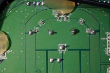
If a resistor is a big one on the pre amp board..there are five in total and they are bigger i think 1 watt or so they are all 2.2ohm. On one sub i saw this. One was burned and black in the middle. I started measuring and what i found out is that ...well every one resistor coresponds to a main amplifier chip tda7294 on other board the bigger one....i found out that one amplifier chip has shorted out pins for output and voltage supply and that produced that 50V power supply go directly to a connection for the speaker. I think that caused the burning of the resistor. I changed the chip amp tda 7294 and the resistor and works like a charm. So I would suggest ..if it is the resistor that i mentioned...that you start by measuring outputs and eventually tda 7294. BUT BE VERY CAREFULL...VOLTAGE INSIDE CAN KILL YOU EVEN IF THERE IS NO CONNECTION TO THE MAINS...
z5500 loud humm from all speakers
Well, my friends, I want to share one more experience that i had with good old z5500.
I came across a system with PID R818. The system was complete: subwoofer of course, control pod and satellite speakers. The problem was that when i turn on the system, immediately started a humm, very loud very very loud humm from sub and from satellites.
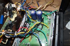
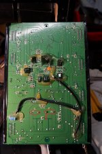
All of them. That made me think that something that is common for all amplifiers inside has gone bad. So the common for all chip amps inside is power supply. 50Volts DC. This comes from 2 biggest capacitors 10.000uF each. So i took a look from the other side and saw that one pin from one cap wasn't quite right. When i looked closely, the pin was free to move in its place. I soldered it and system works like a charm. I think that from vibrations these pins gets loose from time to time...maybe. Well that's it. I am also sending some pictures. All the best from me.
Well, my friends, I want to share one more experience that i had with good old z5500.
I came across a system with PID R818. The system was complete: subwoofer of course, control pod and satellite speakers. The problem was that when i turn on the system, immediately started a humm, very loud very very loud humm from sub and from satellites.
All of them. That made me think that something that is common for all amplifiers inside has gone bad. So the common for all chip amps inside is power supply. 50Volts DC. This comes from 2 biggest capacitors 10.000uF each. So i took a look from the other side and saw that one pin from one cap wasn't quite right. When i looked closely, the pin was free to move in its place. I soldered it and system works like a charm. I think that from vibrations these pins gets loose from time to time...maybe. Well that's it. I am also sending some pictures. All the best from me.
Attachments
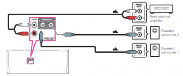
Following this picture I've been able to directly send a signal from my receiver to the subwoofer via a RCA cable.For those who can't view the thumbnail pics from post #485 above, see below. Hopefully Photobucket doesn't zap these later.
Without volume control pots:
However, when it's connected the receiver becomes super sluggish and doesn't respond properly anymore.
When I measure the signal it seems like everything gets drawn from it. Doesn't seem like good behaviour on an expensive receiver. Has anyone managed to get this working with a receiver? Is the above image right?
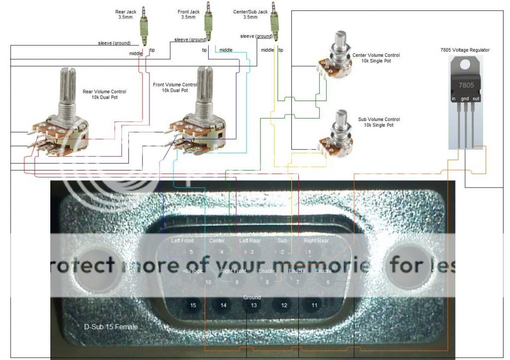
Can't seem to edit my post, so I'll make a new one. This is how I've done it:
The centre of the RCA cable goes to pin 2. The shield goes to 13 (GND). From 13 it also goes to 6 and 7.
From #10 (8v logic) it goes through a 7805 to get 5v and then put that in the #8 to enable the amp.
I believe this is exactly how it's described, and it actually does work. However, it seems to draw the signal from the receiver. It gets very low causing the receiver to act weird... Anyone here that might be able to help me?
Just for the record: my whole Z5500 set is working fine, but I want to upgrade in the future. But because good speakers are expensive I want to do it in steps by first getting a receiver. I've tested it on a Pioneer SC-1223, which by all means isn't a bad receiver.
Can't seem to edit my post, so I'll make a new one. This is how I've done it:
The centre of the RCA cable goes to pin 2. The shield goes to 13 (GND). From 13 it also goes to 6 and 7.
From #10 (8v logic) it goes through a 7805 to get 5v and then put that in the #8 to enable the amp.
I believe this is exactly how it's described, and it actually does work. However, it seems to draw the signal from the receiver. It gets very low causing the receiver to act weird... Anyone here that might be able to help me?
Just for the record: my whole Z5500 set is working fine, but I want to upgrade in the future. But because good speakers are expensive I want to do it in steps by first getting a receiver. I've tested it on a Pioneer SC-1223, which by all means isn't a bad receiver.
Everything seems to be properly connected. The questions:
Is the signal that you bring to z5500 allready amplified by the receiver or it's coming from a pre-out?
Do you hear sounds or music when you play them on z5500 (through a receiver) or not? what is exactly happenning?
What is the PID of the z system?
Thanks for the reply.Everything seems to be properly connected. The questions:
Is the signal that you bring to z5500 allready amplified by the receiver or it's coming from a pre-out?
Do you hear sounds or music when you play them on z5500 (through a receiver) or not? what is exactly happenning?
What is the PID of the z system?
The signal comes from a Pioneer SC 1223 on the sub out port. I have no idea if that's already amplified, but I can't imagine that it is?
The subwoofer is actually playing when it's connected, and it sounds like it should. The only problem is that the receiver becomes unresponsive. When I measure the signal when it's connected it seems to draw it almost empty... I really can't describe what's going on. One thing is for sure: it's not right and I don't think it's any good for my receiver either.
My PID is (the M/N on the back of the sub right?) S-0115B
Well, that's strange. I can't imagine how can a pre-out signal draw the receiver empty. So, I'm sending you a picture. It's the back of your amp. There are two sub pre-outs. I think you can use any one of them. One chinch is for one sub the other is for the second. You only need one. If you connected it from here then and it happens what you described, i would try them separately. Did you try the receiver on other equipment and verify it's ok? At this moment i have no other possibility.
Attachments
I have another custom-built subwoofer to test with. That works fine. I connect them both the same way. The other subwoofer also has a RCA cable running to the amp of the subwoofer which powers it. The only difference is that my receiver works fine with that subwoofer, and becomes slow to input with the Z5500 sub connected. The sub does actually work fine though... That's the strange part. Can it be due to interference from something?
I have another custom-built subwoofer to test with. That works fine. I connect them both the same way. The other subwoofer also has a RCA cable running to the amp of the subwoofer which powers it. The only difference is that my receiver works fine with that subwoofer, and becomes slow to input with the Z5500 sub connected. The sub does actually work fine though... That's the strange part. Can it be due to interference from something?
I'm now stumbling in the dark.....the way i see it is this...the only connection between the z system and the amp is subwoofer preout. So that's the only point where the z sub can influence the amp. the only one. You said the amp works fine so we have to assume that the z system is interfering with the amp. What i would do is measure the pin 2 from the logitech sub with multimeter on dc voltage or ac voltage(relative to the ground). To see if there something there...but on the other side if there was something there that would interfere with the output signal. So that's like a long shot. The other thing is the ground from the signal. Maybe there something wrong with the lm7805 and brings something bad to the pin 13 but that would also proceed to the output signal and you said sub works fine. At this moment i have to get out..at this moment i don't have a solution. One more thing, but that also doesn't hold the water so to say. I had a system with PID R818 and i couldn't turn it on with this schematic on pin 8 and so on i could only do it on pre 636 PID systems. But yours is on and works.
I hope you solve it...
All the best
- Home
- Amplifiers
- Chip Amps
- Hacking the Logitech Z5500