I have a 1000 D Memphis amp i was listening to music with my volts low around 10 and my amp pop and smoke rolled out. I took it apart and about 4-5 of the transitors were melted. I replaced them and the resistors going into them. The board was burt and the metal paths were falling off so i used solder to connect the resistor to one of the legs of the transistor. Can you do that? After puting it all back together it seamed ok till i turned the remote lead on and it pop and burnt 2 of the transitors. One cracked in half. These transistors look to go straight to the ground on one leg and a big coil on the center with a resistor on the 3rd leg. Anyone know what else could be bad. I think i fired something running it at a low voltage. There 22 ohm resistors and IRF3205 transistors. also the heat sink has a ground wire that screws into it but he transitors don't connect to the heat sink there is a cardboard backing and a pad on the amp chassie. So im guessing it's only connection is thought the heat sink screws.
It's likely that the drivers on the vertical PWM driver board have also failed. I think they're using 2SA1266s. They're directly under the PWM IC. If the amp is one of the older ones that has the vertical board soldered into the main board (instead of socketed), be very careful when unsoldering the board. The boards can be easily damaged.
You need to check the output transistors to see if any are shorted.
You also need to check the remote bass control for loose connections. I've seen a couple of these amps self-destruct when they developed bad connections.
You need to check the output transistors to see if any are shorted.
You also need to check the remote bass control for loose connections. I've seen a couple of these amps self-destruct when they developed bad connections.
I return this amp several times, i kept blowing it up because of that dam remote plug. Finaly the dealer installed it and it has been goign good for a yr. But i got the newer 1000D out of it. My PW board just plug in. I looked under the ic on one of the vertical boards and a driver AL1266 was half gone. There are 2 back to back but one still looks good. Is that the same one as the one you were talking about? Also since the path ways on the board are fired near the output transistors can i solder paths?
You need to replace BOTH driver transistors. There's a really good chance that the other is also damaged.
Are the traces on the board actually damaged or are they simply covered in soot that was sprayed onto the board when the FETs failed?
Use some acetone and a toothbrush to clean the board so that you can clearly see the traces. Do this outdoors, in a well ventilated area because the acetone is extremely flammable. Don't use a toothbrush with a clear plastic handle because they typically melt in acetone.
If you can post some high resolution images of the area with the burned traces (if they're actually burned), that would allow us to see what you have.
I replaced the A1266's with A1015's b/c i couldn't find any A1266's. I read that they were pretty basic. I also replaced all the output transistors with IRF3205 same as before just for sake. Now i hooked it all back up and taped the remote to the amp and the red protection lite kept lighting up. So being stupid i held it to see if it would come on and it blew up again. It stayed on for a few sec's then smoke rolled out. Looks like i blew the first 3 output transistors. From what i have read i think the IRF320 are staying on and the few secs was just the time it took for them to heat up. Any thing else keep those running full go?
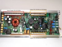
The 3205s are the power supply transistors. Note the location of the outputs in the attached drawing.
When you repair an amp, you need to initially power it up through some sort of current limiter. A 1.5-2 ohm 50 watt resistor in the B+ line works well. If you can't get a suitable resistor, use a 5-7.5 amp fuse. Virtually any amp will power up through a 7.5 amp fuse. If the fuse blows, it's likely that you've missed something.
Possible problems.
*You missed something in the drive circuit.
*The transformer is shorted (relatively rare)
*The rectifiers are shorted (rare)
*The output transistors are shorted (most common cause of power supply failure)
Check the output transistors to see if any are shorted.
Check the driver boards and the area near the outputs to see if there is any other visible damage (burned resistors are most common).
Before powering the amp up, mount it back in the heatsink. If there is a problem, the transistors are more likely to survive if they are clamped tightly to the heatsink.
Attachments
The reason you didn't blow all of the power supply FETs is because you pulled power off of it quickly. I would STRONGLY recommend replacing all 8 3205s. If 4 failed, the other 4 may be weakened even if they are not cracked.
If you have one IRF640 and one IRF9640 blown, you have to replace all of the outputs in that half of the amp. The transistors are connected in parallel and must be relatively closely matched to provide good reliability.
To check the amp, you can power it up with the defective 640/9640s removed. The remaining output FETS will allow the amp to operate at low power. If the amp plays at low volume with the defective outputs removed, there's a good chance that the drivers are OK. If that's the case, replacing all of the outputs in that half of the amp should get it going.
Do all testing with the amp clamped into the heatsink. Don't forget to use a current limiter of some sort in the B+ power supply line.
When you reinstall it, run it for a while without the bass boost cable plugged in.
Im back
Sorry i've been working alot but im back to my amp. I decied to start frest since i've done so much with out a power limiter. I replaced all the output transistors on both sides and the power transistors. I hook it up using a 10a fuse and it blows everytime right away pretty bad blow. got anything...?
Sorry i've been working alot but im back to my amp. I decied to start frest since i've done so much with out a power limiter. I replaced all the output transistors on both sides and the power transistors. I hook it up using a 10a fuse and it blows everytime right away pretty bad blow. got anything...?
Pull the 4 rectifiers (black, fully encapsulated, mounted to heatsink).
If the board isn't marked with a symbol to show where each type of rectifier is used (symbol on rectifier matches symbol on PCB), mark each rectifier before removing them.
Try powering it up without the rectifiers (only for a second or so). If it doesn't instantly blow the fuse as it did before, the problem is likely in the audio section. If the fuse again blows instantly, the problem is in the power supply (FETS, drive circuit, transformer).
While you have the rectifiers out of the circuit, check them to confirm that they're OK.
Replace the rectifiers unless they're defective.
Post the results.
Do you have an oscilloscope?
I took the rectifiers out and there all good.I tapped the power a couple of times and i thought it wasn't gona blow the fuse so i held it on and it blew within a second... i think the caps just had to charge cause i used another fuse and it blew right away.
When i first put power to this amp after replaceing all the mosfet i forgot to attach the wire going to the heat sink but i still had a fuse blow. could i have hurt anything with that not connected
also no i dont' have an isoscope. my friend has one but i don't know how to use it or if he would let me use it.
I have a radioshack multimeter. I talk to my friend and i guess he doesn't have the iso anymore.
-The insulators u are talking about... is that cardboard on the back of the heat plate or the rubber like pad between the frame and the fets?
-I tested for resistance between case and fet tabs andthere wasn't any so i don't belive the rubber pads have and rips.
-The insulators u are talking about... is that cardboard on the back of the heat plate or the rubber like pad between the frame and the fets?
-I tested for resistance between case and fet tabs andthere wasn't any so i don't belive the rubber pads have and rips.
I forgot to mention. After blowing the fuse so quick i double checked all my connects measureing resistance and i found 2 bad connections both involed and output fet with it's resistor not connected.
From what I read said that this would leave the fet open. Could this have broke it? I was using the fuse at this point
From what I read said that this would leave the fet open. Could this have broke it? I was using the fuse at this point
The insulator is the rubber pad between the FETs and the transistors.
If you had an open connection between the gate of the FET and the drive resistor, that well could have caused the failure. With the gate resistor disconnected, the FET's gate charges and the FET switches on. Since nothing switches it off, it acts like a short circuit which could blow it or other FETs.
To check the connection of the gate resistors, you can measure the resistance between the gate of one FET to the gate of another paralleled FET. The resistance from gate to gate will be twice that of a single gate resistor. If you're unsure which FETs are connected in parallel. measure the resistance from one terminal of the gate resistor (the end that's not connected to the gate) to the leg of the FET. If the resistance is the same as the value of the gate drive resistor, the connection is good.
If the board is not clean enough for you to see the solder connections and traces clearly, use some acetone and a toothbrush to clean away the flux and soot. Remember that acetone is very flammable. Clean the board outside where you have good ventilation. Allow the solvent to evaporate completely before you apply power to the board or solder on it.
Fixed!
Yes! So after pulling all the power mosfets i check them and found a bad one it was the one with the gate resistor not connected. I put everything back and double checked all my points and hooked power up and it didn't blow a fuse. So i put a bigger fuse in 20amp and it didnt' blow... I have yet to hook the remote up thought to truely turn the amp on but i think i have got it. i'll update later anything you sugest?
Yes! So after pulling all the power mosfets i check them and found a bad one it was the one with the gate resistor not connected. I put everything back and double checked all my points and hooked power up and it didn't blow a fuse. So i put a bigger fuse in 20amp and it didnt' blow... I have yet to hook the remote up thought to truely turn the amp on but i think i have got it. i'll update later anything you sugest?
If you have the amp clamped into the heatsink, a 10 amp fuse should be safe.
It likely has another problem. If you pull the rectifiers and the amp still blows the fuse, the problem is very likely in the power supply. If the fuse survives with the rectifiers removed, the problem is likely in the audio section.
It likely has another problem. If you pull the rectifiers and the amp still blows the fuse, the problem is very likely in the power supply. If the fuse survives with the rectifiers removed, the problem is likely in the audio section.
- Status
- This old topic is closed. If you want to reopen this topic, contact a moderator using the "Report Post" button.
- Home
- General Interest
- Car Audio
- Memphis 1000D Transistor Blowing