When halfway thru turning up the gain, the amp suddenly burst into life!
I found the problem in the end, the signal ground on the RCA socket on the amp has an intermittent connection...
This explains why I was able to trace a signal thru the whole circuit, as my black probe was clipped on to the outside of the RCA... So my meter was getting a great ground, but the amp wasn't...
Anyway, I've soldered a wire from the RCA ground to correct end of R80, and it is all working! I can't believe that I checked the rca plugs when the board was out the chassis, and they checked out ok... Next time i'll check, double and triple check the RCA's...
I guess you could even croc clip signal wires onto components on the PCB to bypass the RCA's altogether...
I just want to say thanks, this is the first time I've fixed an amp, and I doubt I would have managed it without your help.")
I found the problem in the end, the signal ground on the RCA socket on the amp has an intermittent connection...
This explains why I was able to trace a signal thru the whole circuit, as my black probe was clipped on to the outside of the RCA... So my meter was getting a great ground, but the amp wasn't...
Anyway, I've soldered a wire from the RCA ground to correct end of R80, and it is all working! I can't believe that I checked the rca plugs when the board was out the chassis, and they checked out ok... Next time i'll check, double and triple check the RCA's...
I guess you could even croc clip signal wires onto components on the PCB to bypass the RCA's altogether...
I just want to say thanks, this is the first time I've fixed an amp, and I doubt I would have managed it without your help.
Now that it's working, you should trace the signal through the amp so you'll know what to expect on other amps.
When I suggested that you increase the signal level, it was because the signal levels weren't correct. It appeared that you may have been picking up noise more than anything else. You should have found a signal almost 20x greater on the emitter of Q112 than on the base of Q101.
When I suggested that you increase the signal level, it was because the signal levels weren't correct. It appeared that you may have been picking up noise more than anything else. You should have found a signal almost 20x greater on the emitter of Q112 than on the base of Q101.

Audi-
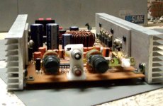
That looks really sweet. Two things: 1) Noticed you're using chip-amps. Might those be LM4765T Overature-series amps? ((Or am I just too lazy to look back thru the thread to see if you listed it earlier? ) If so, how are you running them? Bridged output?; and 2) I have a couple heatsinks that look just like the ones you're using. Now I have a good idea of what to do with them...
Keep up the great work!!
Cheers,
Steve
That looks really sweet. Two things: 1) Noticed you're using chip-amps. Might those be LM4765T Overature-series amps? ((Or am I just too lazy to look back thru the thread to see if you listed it earlier?
) If so, how are you running them? Bridged output?; and 2) I have a couple heatsinks that look just like the ones you're using. Now I have a good idea of what to do with them... Keep up the great work!!
Cheers,
Steve
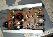
MY SMPS PCB
Hi All,
My SMPS pcb at here:
http://www.diyaudio.com/forums/showthread.php?postid=1785299#post1785299
Hi All,
My SMPS pcb at here:
http://www.diyaudio.com/forums/showthread.php?postid=1785299#post1785299

Thank you! I can get that at a shop here
I took the liberty to attempt to test just the amplifier board today by hooking it up to a 30 volt 5 amp transformer i had around. The signal was a mono 3.5 jack i hooked up to a cd player. All I got was a loud buzzing... I unplugged it after a bit of smoke started coming from the board. All of the transistors stayed cool. I used a 470 ohm trimpot instead of the 330 one called for. As well i used a 2.3k resistor where it called for a 2k2 resistor.
Are my lack luster results due to using a 30-0-30 transformer and a cd player? I may have hooked up the transformer backwards, ie 40+ to 30- and 40- to 30+ as it was a surplus buy and had no markings. If the problem is the board itself I've got a lot of extra parts and I think I'll tear it down and start over. Maybe even try to be a bit more attentive this time...
Lemon,
First, start out by taking raw AC measurements across all the transformer secondaries before you connect them (assumed thru a rectifier & filter cap) to anything! Remember, if you read 30VAC, it's really peaking out at 42.42V, so you will wan to t de-rate your amp's voltage operating points, if possible.
Second, once you have sorted out all the secondaries, connect your rectifier bridge and two caps and measure the (+) & (-) voltages. Once you're satisfied you have good readings, correct any of the damage you mave done to the main amp board, and try it again.
Steve
The bridge rectifier is putting out 36 volts dc. Shouldn't it be 60ish volts between the positive and negative wire? Anyways, I have one 3300 uF capacitor between positive and ground and negative and ground. I tried it again after cleaning up alot of stuff. I did it without a speaker and it stayed cool so I hooked it up to a speaker without a signal coming in and pooff the speaker went up in smoke. It was a free two way speaker with 120 watts max power, but the problem is that there was a hum while it was hooked up... and that it fried...
Why would the amp be putting out so much power with no signal? :| so I'm guessing that means transistors are fried. How can I check this?
Why would the amp be putting out so much power with no signal? :| so I'm guessing that means transistors are fried. How can I check this?
Im slowly working through my errors now. This is my first audio amplifier project, I'm a first year mechanical engineering student and it's quite humbling to learn how little you know!
Will I be able to test this amplifier on my 30 volt CT transformer? Which I now realize is putting out +/-18V DC at 5A max... I hope its sufficient because I'd like to test at a low voltage at first.
Thanks for the help! I'm sure a lot of you hate teenagers coming here requesting how to make a subwoofer amplifier but I'm trying to learn
- Status
- This old topic is closed. If you want to reopen this topic, contact a moderator using the "Report Post" button.
- Home
- General Interest
- Car Audio
- Finished Car Amplifier schematic + PCB based on Kenwood KAC-716