I am looking for some educational links for beginning to work with SMPS supplies... at the moment, that is all greek to me... I'm pretty fluent with typical single and dual rail PSU's but trying to follow Rod's circuit required too much external knowledge not contained in his site...
Plan is to be able to construct a car amp, say 50 to 100W or so...
would it be better to just buy one of those complete inverter units? Although this would severely cut the educational value, not to mention DIY funness..
Plan is to be able to construct a car amp, say 50 to 100W or so...
would it be better to just buy one of those complete inverter units? Although this would severely cut the educational value, not to mention DIY funness..
Vr3 330 Ohms - Power Amp
Hola, quería saber para que sirbe el preset (Vr3 en el esquematico) de 330 Ohms que está ubicado en el pcb del Amplificador. Saludos desde Argentina.
Hello, it wanted to know so that preset (Vr3 in the schematic) of 330 Ohms that is located in pcb of the Amplifier. Greetings from Argentina.
Hola, quería saber para que sirbe el preset (Vr3 en el esquematico) de 330 Ohms que está ubicado en el pcb del Amplificador. Saludos desde Argentina.
Hello, it wanted to know so that preset (Vr3 in the schematic) of 330 Ohms that is located in pcb of the Amplifier. Greetings from Argentina.
My Web Site
For full text, pictures, pcb and schematic for this article visit my web site: www.elkomak.4t.com
For full text, pictures, pcb and schematic for this article visit my web site: www.elkomak.4t.com
Re: My Web Site
http://www.elkomak.4t.com/catalog.html
I see sections of the ESP P89 article and some parts from the valveaudio website copied and pasted to your article but you don't refer to them in any of your texts. I would like to point that out before the copyright owners do something about it.
Risto80 said:For full text, pictures, pcb and schematic for this article visit my web site: www.elkomak.4t.com
http://www.elkomak.4t.com/catalog.html
I see sections of the ESP P89 article and some parts from the valveaudio website copied and pasted to your article but you don't refer to them in any of your texts. I would like to point that out before the copyright owners do something about it.
Hey, I've recently got hold of a non working KAC-716. The light comes on, but nothing comes out the speaker output....
Would it be possible to just use the SMPS from it?
The only problem is that +-40v is way too much for me...
I really want +-12v, as I want to power a 41Hz.com AMP9 module in my car, which needs 24v. I was thinking a 1:1 turns ratio would give me +-12v, but I would need 10A (peak) from each rail... which is probably a lot more current than the KAC-716, so would I end up blowing up the MOSFETS?
Also, anyone know of a good source of toroids or enameled wire in the UK?
EDIT: Also, could someone kindly post up the service manual, it would be a great help for me as I will then know which parts of the PCB do what.")
Would it be possible to just use the SMPS from it?
The only problem is that +-40v is way too much for me...
I really want +-12v, as I want to power a 41Hz.com AMP9 module in my car, which needs 24v. I was thinking a 1:1 turns ratio would give me +-12v, but I would need 10A (peak) from each rail... which is probably a lot more current than the KAC-716, so would I end up blowing up the MOSFETS?
Also, anyone know of a good source of toroids or enameled wire in the UK?
EDIT: Also, could someone kindly post up the service manual, it would be a great help for me as I will then know which parts of the PCB do what.
I've e-mailed a mod asking exactly that...Perry Babin said:1:1 would give you approximately ±12v with ~13v in.
The lower ratio would reduce the demand on the FETs so they should easily survive.
If you're interested in continuing this thread, have a moderator split this off to a new thread.
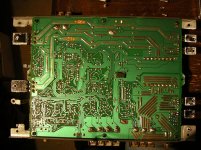
I've just tested the rails on the amp (with no load)...
It seems one of the rails is a little low at -21v.
Attachments
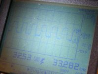
When you say rectifiers do you mean D206 and D207? I've checked the outside legs on D206 and D207, and they are both getting a square wave, 32Vrms @ 33khz according to my Fluke 863.Perry Babin said:Check the legs on the rectifiers. One may be broken.
This is measuring from one of the outside legs to ground. Here is a photo of the wave:
EDIT: Could it be one of the 50v 1500uF caps that has gone?
Attachments
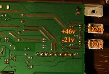
Well, the voltage on the center leg of D206 is fine, as it measures as 46v.Perry Babin said:The voltage on the center leg should be the same as the peak voltage of the square wave on both the top (for the positive rectifier) and the bottom (for the negative rectifier). Is this the case for both rectifiers (yes, D206 and D207)?
But the voltage on the center leg D207 is a little low, at -21V, which seems strange. If the rectifier was broken, shouldn't it read 0v?
This is why I think it could possibly be one of the 1500uF caps...
I've blown up the part with the rectifiers to make things a little clearer (I hope).
Attachments
Well the caps looks visually fine, no bulges or goo... so a bad rectifier makes more sense.Perry Babin said:If you have the same signal on the outer legs of BOTH rectifiers and the DC on the output of the negative rectifier (on the center leg) is clean (no excessive ripple), the negative rectifier has to be defective.
As far as ripple goes, 46v on the middle leg of D206 is pretty ripple free.
The -21v on the middle leg of D207 has a bit of ripple, around 2-4v above and below the -21v line... I'll see if I can get a good pic somehow.
FWIW, Here's what It says on the rectifiers:
D206 =
FMU22S
-->|---|<--
8531
D207 =
FMU22R
--|<--->|--
8606
Also, I can quite easily cut to wires on the top of the PCB to isolate the output of D207 from the caps... Would this help at all?
How similar is the Kenwood 816 to the 716? Power rating looks similar...
As for info on building SMPS for car amps... there's a pretty good article in Audio Amateur, back around 1988 by Randall K. Vikan. I'm pretty sure it is reprinted in an Audio Amateur book of amplifier projects.
As for info on building SMPS for car amps... there's a pretty good article in Audio Amateur, back around 1988 by Randall K. Vikan. I'm pretty sure it is reprinted in an Audio Amateur book of amplifier projects.
It won't be until tomorrow until I'll be able to find the soldering iron, as it's 1am here, and I don't want to wake the others in my house...Perry Babin said:Desolder D207 and check it out of the board.
Anyway, I cut the wires linking the centre leg of D207 to the caps, and I'm still getting the same reading... -22v
I'll desolder it tomorrow, and check it out of the circuit.
Also, the part doesn't seem to be available any more, but I managed to dig up some info on it...
http://www.americanmicrosemi.com/information/spec/?ss_pn=FMU22R
I guess if I was going to have to get a replacement, I'd have to match the specs, or would it be better to change both rectifiers at the same time so the specs would match?
I'm going to get some sleep now, thanks very much for the help. My plan is it get it working at +-40v first, then change the transformer for one with a 1:1 ratio.
Another option would be to use a 1:2 ratio toroid, and just use the output from the 1 good rectifier, as my AMP9 module only needs +24v, as opposed to +-24v. Would this be possible?
There are lots of substitute rectifiers available.
The positive and negative rectifiers don't have to match. Unless D207 is broken physically, I wouldn't change both. If D207 is broken physically, I'd suggest changing both because they would have received the same stress and D206 may be ready to break. If you don't find that the legs are broken inside the case of the rectifier, I'll be surprised.
If you're going to use this in your vehicle, you'll have to break the ground for the secondary side of the transformer. It appears that the metal buss bar may be the connector for the two grounds. If so, you'd have to cut it or remove it.
I don't know enough about the amp9 to determine if a single supply or a dual supply would work best. The 41hz site indicates that it uses a single-ended supply. You should ask someone in the class D forum which supply would be the best for that amp.
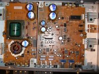
I do plan on using this in the car - I'm not sure what you mean by breaking the ground for the 2nd side of the transformer... I plan to replace the transformer anyway, as 40v is too high for my AMP9.Perry Babin said:If you're going to use this in your vehicle, you'll have to break the ground for the secondary side of the transformer. It appears that the metal buss bar may be the connector for the two grounds. If so, you'd have to cut it or remove it.
I've attached a pic of the top of the PCB which may help.... I should be able to get the big metal thing out without a problem tho.
Well I'm using the AMP9 in the house on a single ended supply and it works great. In fact I now think it would be better to go single ended, and the ground for everything would be the same... I may get ground loops from my headunit if I go with +-12v supply...Perry Babin said:I don't know enough about the amp9 to determine if a single supply or a dual supply would work best. The 41hz site indicates that it uses a single-ended supply. You should ask someone in the class D forum which supply would be the best for that amp.
So for single ended I guess I would still need a centre tapped 1:2 toroid to replace the existing transformer to get +24v, and simply not wire anything up to the -ve rail... Perhaps it would be best to leave D207 out of the PCB one I have de-soldered it...
EDIT: I think I know what you mean about not connecting the secondary ground to the PCB. As I'm replacing the transformer anyway, I can simply not wire it up to the PCB. I can also remove all the 1500uF caps and simply wire them up outside the PCB.
Attachments
- Status
- This old topic is closed. If you want to reopen this topic, contact a moderator using the "Report Post" button.
- Home
- General Interest
- Car Audio
- Finished Car Amplifier schematic + PCB based on Kenwood KAC-716