When I turned the gain up, then the distortion became less audible.
That definitely sounds like crossover distortion.
Its usually worst at low signal levels.
What's the rail voltage in the amp?
What's the DC voltage across the B+ and ground terminals?
Rails: +22,1V and -20,4V
DC across B+ and ground: 11,3V
Voltage on opamps: +11,0V and -10,8V this dropped because I was using car battery to power the amp when I took the first measurements, now I switched to my PSU.
If you have the regulators, you could use those in place of the Zener regulators. You'll probably have to use heatsinks on them or drill and tap the heatsink to allow you to mount them to the heatsink.
For now, get the regulated voltage up to ±15v by modifying the value of the resistors feeding the Zeners. If the distortion is eliminated with the ±15v, you can use whatever you'd like to supply the ±15v to the amp.
For now, get the regulated voltage up to ±15v by modifying the value of the resistors feeding the Zeners. If the distortion is eliminated with the ±15v, you can use whatever you'd like to supply the ±15v to the amp.
Tried replacing it with 270 ohm (original was 680) and one time left accidentially base-emitter resistor unconnected to the board, sine looked the same each time.
And then I discovered that the 1K resistor, which I claimed was connected between base and collector of that transistor, is actually connected to base of that transistor and source of one of the output transistors. Oops.
And then I discovered that the 1K resistor, which I claimed was connected between base and collector of that transistor, is actually connected to base of that transistor and source of one of the output transistors. Oops.

If you draw a diagram, look through the audio sections of the schematics under the 'Power Supply Driver Circuits' (item 33 on the Power Supply Troubleshooting page). It's likely closest to the OV_SCH.pdf in the power acoustic folder. The differential amp and VA stage should be close but the output stage will be different.
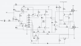
Finally managed to draw the schematic. I looked at various schematics but did not find a similar one, probably did not pay attention. So I started from scratch, drew it twice, but still did not get it to look very good, but I hope you can get the info you need to guide me further with this. I may have made some mistakes, if something does not add up at all, let me double check.
Schematic is attached.
Schematic is attached.
Attachments
Decreasing RA27 or increasing RA20 did not help, output is still the same. Tried it with and without the modification to 15V regulator, which we tried earlier. I just realised that when I was drawing the schematic, then I was looking for the point to which +/-15V is connected in the channel with my DMM . I did not find it, instead there was +/-30V, which is taken straight from the transformer through a diode.
- Status
- This old topic is closed. If you want to reopen this topic, contact a moderator using the "Report Post" button.
- Home
- General Interest
- Car Audio
- Cheap amp distorted output