Hello
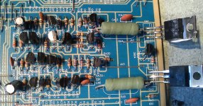
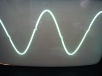
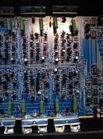
I bought two 6 channel, very cheap, amplifiers. They were sold as defective. At first the only sign of them being defective was that on one of them the gain pot had broken off the board, I replaced that. Audio is distorted on all of the channels on both amps. I attached a picture of one channel from one amp and picture of scope screen of 1000 Hz sine on output with speaker connected. When probing outputs without speakers, output looks good on scope screen. All channels are the same. By the looks of it, no repair work has been done on the amplifiers, besides me changing the gain pot on one of them. Amp uses 2 IRF540N-s as outputs for one channel. I am using PSU to test the amp, voltage on power terminals is about 11,5V.
Once I had a similar issue with one amp and Mr. Babin told me to increase the resistance between bias transistors base and collector. This is the fix this time around also?
Attachments
I tried to find the bias transistor using the help of Perrys tutorial and the previous thread I started on a similar problem: http://www.diyaudio.com/forums/car-audio/218258-amp-distorted-output.html
But I am a noob at this and did not find the bias transistor. My guess was that transistor between outputs should be the bias transistor, but it is not connected the way Perry described how bias transistor would be situated in the circuit. I think it is because instead of using IRF9540 and IRF540 as outputs this amp uses pair of IRF540-s in each channel.
But I am a noob at this and did not find the bias transistor. My guess was that transistor between outputs should be the bias transistor, but it is not connected the way Perry described how bias transistor would be situated in the circuit. I think it is because instead of using IRF9540 and IRF540 as outputs this amp uses pair of IRF540-s in each channel.
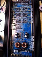
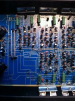
Post a photo of the entire board.
If it uses all N-channel FETs, it should function the same. If you increase the value of the resistor that's connected between base and collector of the bias transistor that should increase the bias current.
You could alternately decrease the B-E resistor for the bias transistor.
Some amps that use all N-channel outputs set the bias through the differential amplifier pairs. Confirm that you have at least ±12v on the power supply pins of the op-amps.
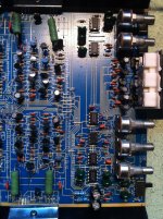
There are 1K ohm and 680 ohm resistors connected to the transistor which I suspected was the bias transistors. Added 100 ohm and 220 ohm resistors to those in series and in parallel but output was distorted with every configuration.
There were -11,9 and +12.0 volts on power supply pins of op-amps. I replaced one op-amps also to see if that would make any difference, it did not. Added photos of the board.
There were -11,9 and +12.0 volts on power supply pins of op-amps. I replaced one op-amps also to see if that would make any difference, it did not. Added photos of the board.
Attachments
Connecting 220 ohm resistor from base to emitter did not decrease distortion.
I wondered about the 12V myself, I read 12V across the Zeners although they are 1N4744A 15V 1W Zeners. There is 12V on pins 6 and 7 of IC3 but it seems that these pins are tied together and connected to nothing.
I wondered about the 12V myself, I read 12V across the Zeners although they are 1N4744A 15V 1W Zeners. There is 12V on pins 6 and 7 of IC3 but it seems that these pins are tied together and connected to nothing.
The load on the regulators may be too great to allow the Zeners to reach their rated voltage. Try replacing the 220 ohm resistors with a slightly lower value or parallel another resistor across each of the 220 ohm resistors (incrementally add 1k resistors would be one way to do it) to see if you can get the voltage up to 15v. If you can, re-check the distortion. It could be that there is insufficient voltage to allow the differential pairs to be properly biased.
Parallel 1k resistors onto the 220 ohm resistors to lower the effective value. 1/4w 1k resistors can take about 12v. Is the drop across the 220 ohm resistor greater than that?
Do you have any L7915 and L7915 regulators?
What's the rail voltage in the amp?
What's the DC voltage across the B+ and ground terminals?
Do you have any L7915 and L7915 regulators?
What's the rail voltage in the amp?
What's the DC voltage across the B+ and ground terminals?
- Status
- This old topic is closed. If you want to reopen this topic, contact a moderator using the "Report Post" button.
- Home
- General Interest
- Car Audio
- Cheap amp distorted output