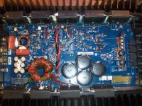
Hello I have a RF type RF X6 in for repair. The board number is PC-3757-D.
I powered the amp and it was powering up drawing a little much current but slowly bleeding down to normal draw and staying there. The amp is in protect.
There is no DC on the output terminal and the amp is producing around 90v rail.
I removed the cover. I first replaced U21 and same result powered up in protect. I then noticed a component not looking right on the board. The component was a MC340 64P-5 which is a under voltage sensing circuit.
Leg 1 which is the reset was soldered to a solder bridge bewtween pins 1 and 2 of the LM339D, Leg 2 which is input was soldered to R65 a smd resistor marked 4120, Leg 3 which is ground was soldered to a spot on the board which obviously must be connected to ground but without removing alot of components or having a schematic I have no idea where it goes.
I thought to remove it and power up the amp. I did. The amp now stays powered up even with the remote wire removed. You have to unhook power or ground then it shuts off. It will stay powered up unless you remove the power or ground even if the remote is used to power the amp initially but then unhooked.
I looked a little closer under the magnifying glass and found pin 13 of the LM339 to be burned off of the IC or removed by someone, this pin is OUT4 on the data sheet.
I know the LM339 can shut down the amp for low voltage and thermal protections and I was wondering if it could trip the protect light as well? The board looks to be set up like a BD1000 just a little fancier with TO-247 outputs instead of TO-220. Thats why I suspected U21 upon first thoughts.
I will be replacing the LM339D just wanting some input from anyone who is interested and thinks this is an odd problem. I must fix the LM339D before I can further troubleshoot, and then move on to testing the outputs and such to see if a shorted output is setting the protect light off.
Any help would be great!!!
Last edited:
OK I replaced the LM339 and the amp powers up and down fine now but still in protect. I found C13 was burned in half which connects pin 7 of U7 and U8 to something.
I am not sure what part number C13 is it is one of the little rectangular capacitor orange in color. The ones around it are marked 104V N0 103.
I will replace U18.
For a future reference just in case I have shorted outputs where can I find a sub for SFH154 and SFH9154 every where I look says obsolete!!!
Tantalum is a type of capacitor similar to an electrolytic but instead if using long aluminum plates, it has an internal structure with a rough surface that produces a very large effective surface area which allows them to produce relatively high capacitance with relatively low ESR in a small package.
If you order replacement tantalums in the same package, be careful when soldering them into the circuit. The negative terminals are sometimes sensitive to heat.
If you order replacement tantalums in the same package, be careful when soldering them into the circuit. The negative terminals are sometimes sensitive to heat.
I put a cap in the place of C13, and changed the opto-coupler U15 the HPCL A2211. No difference power up, protect light goes off, squeeling and current draw. I cant keep the amp powered up but for a second or two so its hard to troubleshoot.
Which resistors disconnect the input and or audio section? Is it R35 and R31 or R32 like the bd1000?
Which resistors disconnect the input and or audio section? Is it R35 and R31 or R32 like the bd1000?
Please read post #13 first.
Why do I have full rail voltage on pins 5,7,8 of the other opto-coupler and full rail on all the pins of the MIC4420CT?
The side I replaced the driver and the coupler on does not have rail voltage on any pins but the other side has full rail on the pins mentioned above.
I know this cant be right what do you think???
Last edited:
I was going to change U17 as that component had been a problem in the past with other amps, but I wanted your opinion first as not to change parts uneeded like I have done in the past you know?
I will check pin 7 of U11 and change U17 then re-install R35 and let you know what becomes of it.
I will check pin 7 of U11 and change U17 then re-install R35 and let you know what becomes of it.
- Status
- This old topic is closed. If you want to reopen this topic, contact a moderator using the "Report Post" button.
- Home
- General Interest
- Car Audio
- Rockford Fosgate Type RF X6