I have not looked at the FETs yet. They don't seemed to have melted yet. The resistors are the only thing that looks fried. I'll replace those first and then move onto the fets. I'll also do some solder maintenance. I've had the amp for over 10 years at least and gave me no issues til the other day when it was 105 degrees outside and the car was even hotter. Have it bridged to 1 ohm. dual 4 ohm voicecoils in parallel bridged to amp. haven't had an issue in forever.
Those won't fail unless the FETs have failed. Unless someone previously repaired the amp and didn't replace the resistors, the FETs are defective.
You should also buy the replacement driver transistors. The 2N2222 is likely available but the 2SA1562 is harder to find. The BD140 can be used as a substitute but the pin configuration is reversed so it will have to be installed facing the opposite direction.
I wouldn't solder anything unless it absolutely needs it. I've seen too many instances where someone inadvertently created a solder bridge and it took hours to find the bridge.
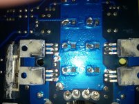
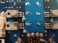
What would be the model number for the FETs and where would be the best place to find them at?? Which FETs would be blown then? The one's right after the resistors??
And which piece is the replacement driver transistors?? If you have an email I can send you pics of the FETS and such. I'm having an EE friend do the solder work. But i suppose if I put just the resistors in I'm guessing they will also blow too? Glad you wrote me back now I'm waiting for parts to arrive.
And which piece is the replacement driver transistors?? If you have an email I can send you pics of the FETS and such. I'm having an EE friend do the solder work. But i suppose if I put just the resistors in I'm guessing they will also blow too? Glad you wrote me back now I'm waiting for parts to arrive.
You should also buy the replacement driver transistors. The 2N2222 is likely available but the 2SA1562 is harder to find. The BD140 can be used as a substitute but the pin configuration is reversed so it will have to be installed facing the opposite direction.
This is the section I was asking about what the driver transistors were. And where were they located on the amp. And thanks for the fet part number. I'll be ordering those too.
This is the section I was asking about what the driver transistors were. And where were they located on the amp. And thanks for the fet part number. I'll be ordering those too.
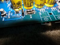
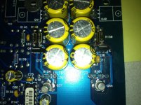
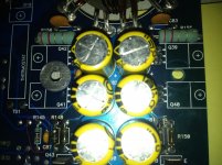
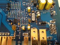
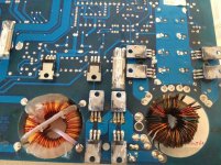
yes. can you post pics of the board? there is also one more resistor to look at. it is common to fail along with the power supply and/or output issue. probably the wrong number in my schematic, but mine says "r145" anyways, it should be a 10ohm 1, or 2watt below the rail caps, if the terminals face down. it connects the rail common to battery negative. i have also seen it in different resistance, but 10 ohm seems to be the most common.
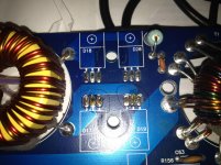
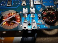
Ok I will be adding some pictures of the amp. Perry, I have some of the compentents circled to verify they are the right ones to look at for the driver resistors, just wondered because they seem to be 2 different components. These are the Q 37, 44, 43 and 38. The other pictures have are of the fets and such and maybe some bad solder spots on the amp that i should also look at. AKheathen. I also have the R145 in the pictures, but that one seems to be fine.
Attachments
- Status
- This old topic is closed. If you want to reopen this topic, contact a moderator using the "Report Post" button.
- Home
- General Interest
- Car Audio
- Soundstream 500 resistor help