FM reception?
The caps on the input boards on a lot of these amps leaked and cause the symptoms you described. Do you see any corrosion on the board behind the RCA jacks?
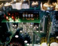
Y-E-S. It looks like an oily substance on the base of at least one of the silver caps on the preamp card. i had to look carefully for it though.
Last edited:
If the damage is minimal, they can be repaired. If the damage is more significant, repair can be tough and replacement is a better option if you can find a replacement.
Can you post a photo of the board?
it would be hard to see with my low res laptop webcam but here goes. i noticed that the solder traces under one cap to the top left 4 (the ones leading to the ic) was corroded badly after i took a q-tip dipped in alcohol to it to clean off the corrosion. i didnt see it until i was able to clean off the grime from the electrolyte. i swabbed the affected area of the circuit while the amp was still hooked up (to my computer power supply and a crappy test speaker of course) and i noticed that the noise came and went when i moved the swab over it. the other caps are fine. it looks like it would be a PITA to replace the caps since they are so close together.
Attachments
Last edited:
All of the capacitors will leak eventually and will continue to cause damage if they're not replaced.
There is little space between them and you'll need a thin soldering iron tip to get between them when you solder the replacements in.
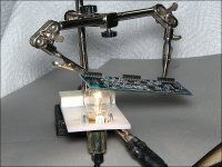
In the attached photo, you can see a simple heater using an 1157 brake lamp. I've used this many times when replacing capacitors and various SMD ICs. If you use something like this, position the board so that the bulb is touching the board directly under the cap. Apply heat to the top of the capacitor with your soldering iron. You'll need to wear safety glasses when doing this. When the solder is molten the cap will slide off its pads. Move the iron gently back and forth so that you can tell when the cap is free. When replacing the caps, Solder the 4 in a row in first then the other two.
Do NOT touch the bulb, do not leave the board on the lit lamp for longer than absolutely necessary and do not look directly at the bulb when it's lit.
There is little space between them and you'll need a thin soldering iron tip to get between them when you solder the replacements in.
In the attached photo, you can see a simple heater using an 1157 brake lamp. I've used this many times when replacing capacitors and various SMD ICs. If you use something like this, position the board so that the bulb is touching the board directly under the cap. Apply heat to the top of the capacitor with your soldering iron. You'll need to wear safety glasses when doing this. When the solder is molten the cap will slide off its pads. Move the iron gently back and forth so that you can tell when the cap is free. When replacing the caps, Solder the 4 in a row in first then the other two.
Do NOT touch the bulb, do not leave the board on the lit lamp for longer than absolutely necessary and do not look directly at the bulb when it's lit.
Attachments
All of the capacitors will leak eventually and will continue to cause damage if they're not replaced.
There is little space between them and you'll need a thin soldering iron tip to get between them when you solder the replacements in.
In the attached photo, you can see a simple heater using an 1157 brake lamp. I've used this many times when replacing capacitors and various SMD ICs. If you use something like this, position the board so that the bulb is touching the board directly under the cap. Apply heat to the top of the capacitor with your soldering iron. You'll need to wear safety glasses when doing this. When the solder is molten the cap will slide off its pads. Move the iron gently back and forth so that you can tell when the cap is free. When replacing the caps, Solder the 4 in a row in first then the other two.
Do NOT touch the bulb, do not leave the board on the lit lamp for longer than absolutely necessary and do not look directly at the bulb when it's lit.
i've never seen anything like this used. the experience i have had with electronics repair is mainly hands-on/hobby/diy and not professional work. i dont own any shop or specialized equipment like i have seen you own on your website and around the internet, nor have i been to any kind of school (although i am working for a pc repair certificate in my local community college).
i have noticed that it very easy to burn the traces on an smd. so the light just assists in the heating of the solder?
Last edited:
It depends on how badly they're damaged and where they are. Small strands of wire will work where the traces are not under the components.
The ICs are op-amps.
I heard there are brand new cards for these amps. This seller on Ebay has the driver boards for the right and left channels and the PWM driver, but I cannot find the board for the preamp input section, which is where I am having the problems. Do you have any idea where I can get a (ideally new or new-old stock) preamp board?
Here's the seller: Rockford Fosgate DSM Driver Board Package!!!! | eBay
Last edited:
Did you contact the seller to see if he had the boards that you need?
Yes. His reply when I inquired on the preamp board is as follows:
I have a few local companies looking them over but its hard to find someone to make them as needed. They want you to commit to buying like 1000 or so. Dont have that kinda money. Although if I can find someone to make a couple hundred I could corner the market and make some cash. I will keep in touch. I have found a few used boards that need repaired but they have trace damage. I might just repair one and send it to you and let you try it. I am pretty good at repairing them.
This was a while ago and I haven't heard from him since, even though he still has the other boards up for auction. This might be an awesome place for even you to look into if you repair these amps. I'm still waiting on updates.
Last edited:
I don't think I've ever seen one of the fiberglass boards that couldn't be repaired. The ceramic boards are a bit more difficult to repair but there isn't enough demand to justify the cost of producing identical boards. You could make replacement boards for the ceramic boards out of fiberglass but again, it probably wouldn't be profitable.
I don't think I've ever seen one of the fiberglass boards that couldn't be repaired. The ceramic boards are a bit more difficult to repair but there isn't enough demand to justify the cost of producing identical boards. You could make replacement boards for the ceramic boards out of fiberglass but again, it probably wouldn't be profitable.
That would be nice if one could get a pcb scan (as well as a parts list of the components) that can be printed on a laser (toner) printer and make a replacement on the cheap the Thomas Gootee way where you print out the layout on a piece of cheap photopaper (like the cheap Kodak Wal-Mart has), use an iron to stick the plastic toner on the paper to a copper blank, soak the paper off the board with water so the toner is left behind, use one part muriatic acid and two parts peroxide to etch the board, and make one at home. The parts might cost too much to make that worthwhile, though.
Last edited:
Ferric Chloride and Ammonium Persulfate are probably safer for most users.
You can get the schematic diagram from Rockford. You can download and use the free version of Eagle (layout editor).
I've used the toner method but it's difficult to get good quality without a lot of trial and error.
The presensitized/photo etch boards make better quality boards but with an increased initial cost.
My preference is a boardhouse that takes small quantity orders. I prefer PCBFabExpress. In small quantities, expect each board to cost $25. At higher quantities, the price per board may be as low as $6. But even after you have the board, you have to assemble them. For that, through-hole parts are easier to handle and solder. You can use solder paste for SMD components but that takes a bit of practice as well to do well.
Ferric Chloride and Ammonium Persulfate are probably safer for most users.
You can get the schematic diagram from Rockford. You can download and use the free version of Eagle (layout editor).
I've used the toner method but it's difficult to get good quality without a lot of trial and error.
The presensitized/photo etch boards make better quality boards but with an increased initial cost.
My preference is a boardhouse that takes small quantity orders. I prefer PCBFabExpress. In small quantities, expect each board to cost $25. At higher quantities, the price per board may be as low as $6. But even after you have the board, you have to assemble them. For that, through-hole parts are easier to handle and solder. You can use solder paste for SMD components but that takes a bit of practice as well to do well.
Aww, I see. You would have to get two printouts, one for each side and then line them up as this is a double sided board, which would be pretty hard to to without through holes. I have made an amplifier from scratch using a TDA-7384 IC that worked well with this method, but that was through hole and a one sided board. Just a thought, though.
I still have that schematic you emailed me a while back for that amp.
Last edited:
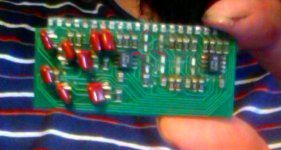
I've got some good news. I was finally able to remove the defective card from the main board using an exacto knife and a soldering iron to gently remove enough solder to wiggle it free, and finally remove the 6 silver 10uf caps by gently rocking each one back and forth to break the solder joint. Thank my lucky stars I didn't break ANY of the solder traces under the caps. It turns out that the damage to the traces wasn't as severe as I saw first glance. A LOT of yellow crud electrolyte did leak out (all caps leaked) and the worst damage was noted on one trace coming from the op-amp in the left in the picture as marked using GIMP. There is a good possibility I might be able to remove the electrolyte a little easier being now the caps aren't in the way and causing problems, and solder new caps in (as the traces are pretty much all intact). I have attached a picture of my work that shows where the worst electrolyte corrosion took place, marked by the red lines.
One quick question: is it possible for someone to soak the card in alcohol or other similar solvent for awhile to completely dissolve and remove the electrolyte from the board (including any that has soaked into the board) in order to help get into ALL of those nooks and crannies, or would that ruin the board or any components? I am asking because the electrolyte conducts electricity and could very well be causing the problems too, and a q-tip just doesn't get into those tight places as well.
One quick question: is it possible for someone to soak the card in alcohol or other similar solvent for awhile to completely dissolve and remove the electrolyte from the board (including any that has soaked into the board) in order to help get into ALL of those nooks and crannies, or would that ruin the board or any components? I am asking because the electrolyte conducts electricity and could very well be causing the problems too, and a q-tip just doesn't get into those tight places as well.
Attachments
Last edited:
- Status
- This old topic is closed. If you want to reopen this topic, contact a moderator using the "Report Post" button.
- Home
- General Interest
- Car Audio
- old school rockford punch 40dsm messes up fm reception horribly.