Howdy,
I got a Power Acoustik BAMF 5500 that produces no audio output. I've got 115v +/- on the rectifiers, no DC on output terminals, actually I've got 0.0000v on terminals(seems strange because I've never had that exact of a number before, they are not shorted though), I can't trace down the audio signal because as soon as they go through the first 15,000ohm resistor the signal is no longer usable.Output voltages are as follows -
IRFP264N
NEG
Gate -115
Drain 0
Source -116
POS
Gate 0
Drain +115
Source 0
Edit : Customer said he was "beatin' on it pretty hard when it cut out", I hear the relays click during power on and power off, but I'm not sure how the power acoutiks go about clamping the signal.
Last edited:
I do not, before when I wrote I had zero output signal, after doing some probing I've managed to get a VERY small output on audio components, not sure how it came about but it's only ~10mV that does correspond with the input sine wave.
Kinda scratchin my head on this one.....
The relays appear to be fine, visually, but I have not checked for sure. How does this amp go about clamping the signal?
Kinda scratchin my head on this one.....
The relays appear to be fine, visually, but I have not checked for sure. How does this amp go about clamping the signal?
Is there any significant DC on the output pins of the op-amps near the RCA jacks?
I have half a volt on one, the rest are ~3mV
1/2v seems a bit high.
Do you have audio reaching the class D driver board?
If not, have you followed it through the op-amps to see where it stops?
Yes, I do have audio in the driver board. As to where it starts and ends, I'm not sure. My "specialty" has been in older A/B amps, with only about 15% of my business being class D, you'll have to excuse my ignorance.
The relays connect the small inductor to the positive speaker terminals. Do you have the board out of the sink?
I do now
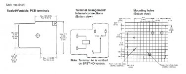
") I'm trying to figure out the pin configuration, I got frustrated trying to find a schematic on them.
I'm trying to figure out the pin configuration, I got frustrated trying to find a schematic on them.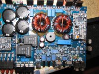
I reflowed the solder just to make sure, still the same senario.
I did noticed that the coils of the relays are directly connected to B+ and B-.... this doesn't seem right to me, the relays are on with only having B+ and B- connected....
EDIT: Also, if this were a typicall relay, where would 87a(pin 4) connect to? Does this pin have anything to do with the driver board "running"? I still don't think that the driver board is working correctly because of the very weak drive signal.
Last edited:
The orange line is the connection between the inductor and the relay. The yellow line is the path from the relay to the terminals.
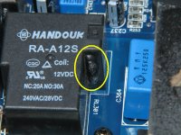
The photo of the relay shows typical damage when the relays fail.
The high current terminals of the relay shouldn't have any connection to the B+ or ground terminals.
Can you post a photo of the drive signal on pin 1 of the IR2110S driver IC?
The photo of the relay shows typical damage when the relays fail.
The high current terminals of the relay shouldn't have any connection to the B+ or ground terminals.
Can you post a photo of the drive signal on pin 1 of the IR2110S driver IC?
Attachments
The orange line is the connection between the inductor and the relay. The yellow line is the path from the relay to the terminals.
The photo of the relay shows typical damage when the relays fail.
The high current terminals of the relay shouldn't have any connection to the B+ or ground terminals.
Can you post a photo of the drive signal on pin 1 of the IR2110S driver IC?
From the schematics of your diagram, pins 2 and 6 go directly to the power terminals, on a bosch relay they would be equivalent to pins 86 and 85. When those terminals get 12v, pin 5 switches to pin 3 connecting the inductor to the positive output terminals. Still stumped as to why the relays turn on only with B+ connected and not remote, somthing shorted?
Pin1 of the IR2110S has 115v DC on it.
Last edited:
+115 or -115?
Any drive signal?
Are the relays connecting the inductor to the positive speaker terminals properly (~0 ohms between inductor and positive speaker terminals)?
Is Q71 shorted? Edit: Not Q71. The transistor against the relay.
Yes, when the relays turn on they are connecting the inductor to the positive speaker terminals, Yes, that transistor is shorted and it was -115v on pin 1.
Was there any drive signal on pin 1?
You may have to set the scope to AC coupling. Set the vertical amp to 10v'div and the time base to about 5uS.
I'll be sure to try that, I know before I wasn't able to lock onto any drive signal at all. I'll get back with you tomorrow evening. I gotta get to bed so that I can teach students about ohms/watts law tomorrow..... yay
.Thanks for your help, Perry.
- Status
- This old topic is closed. If you want to reopen this topic, contact a moderator using the "Report Post" button.
- Home
- General Interest
- Car Audio
- Power Acoustik BAMF5500, no output