hey perry,
alright, the right channel is the problem child.
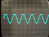
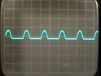
i have a 1v p-p signal being applied.
the first pic is the left channel output, 10v p-p.
the second pic is the right channel with same input applied but at 2 volts per division.
i have 4 ohm resistors on the output.
i'm a little baffled right at the moment.
alright, the right channel is the problem child.
i have a 1v p-p signal being applied.
the first pic is the left channel output, 10v p-p.
the second pic is the right channel with same input applied but at 2 volts per division.
i have 4 ohm resistors on the output.
i'm a little baffled right at the moment.
Attachments
belay that last post about the 5v p-p output, i apparently had the left channel gain set up higher than the right channel.
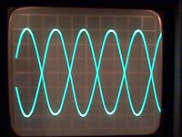
both outputs look good. now to adjust the bias.
got the bias adjusted.
eta:
pic is the left and right output at 5v per div.
both outputs look good. now to adjust the bias.
got the bias adjusted.
eta:
pic is the left and right output at 5v per div.
Attachments
Last edited:
What do you think this is, a self-service forum? You're supposed to make us feel like you need our help.")
lol...
hey perry, thanks so much for the assistance.
trust me, i am sure i will asking for more help!
- Status
- This old topic is closed. If you want to reopen this topic, contact a moderator using the "Report Post" button.
- Home
- General Interest
- Car Audio
- fosgate g250_a2 bias problem