Hi Guys,
I currently have two old Coustic Design Reference amps a 505 and a 514, which I'd really like to be able to use in my current install, problem being they both have noise problems. When hooked up in the car or out of car to a seperate 12v Power Supply I'm getting a hissing noise and it's loud enough to be heard in the car even with the engine running. Now since I've tested these out of car that has basically outruled everything but the actual amps themselves.
Now I'm lead to believe that this kind of noise can sometime be caused by dead capacitors in the Power Supply something to do with ones related to noise filtration. Is this true, and is it the most likely cause? And is it case of just replacing all the Electrolytic caps throughout the amp, or just the ones throughout the Power Supply section or does it involve more then that?
Here are some links to pics on Ampguts , the 514 http://ampguts.realmofexcursion.com/Coustic_514-DR/inside1.jpg
the 505 http://ampguts.realmofexcursion.com/Coustic_505-DR/inside1.jpg
Thanks for any help.
Luke
Replacing all of the electrolytics capacitors with the proper types/sizes/ratings would be a major job.
You stated that the noise was audible when the engine was running. In many vehicles, you can't tell if the engine is running or not so that doesn't tell us much.
Is the noise affected by the gain settings on the amp?
Is it affected by any of the other controls on the amp?
You stated that the noise was audible when the engine was running. In many vehicles, you can't tell if the engine is running or not so that doesn't tell us much.
Is the noise affected by the gain settings on the amp?
Is it affected by any of the other controls on the amp?
The first thing I did after trying a few things in car was take it out and bring it inside to put on a test bench running of a 12V PSU and the noise is still there, so it has nothing to do with the car. My engine although not loud is definitely audible at idle.
Adjusting the gains does not appear to make have any effect that I can tell, weather they are at min, just of min, or cranked right up.
The only other controls are the Balanced Input OFF/ON switch as the amps has two RCA inputs per channel and also has a separate gain per channel. I'm using it in unbalanced configuration so I'm only using the + RCA inputs with the Balanced switch in the OFF position.
But what I did try was to make up some muting/shorting plugs and I tried the amp in unbalanced as well as balanced set-up, and the noise doesn't change, nor did the muting plugs make any difference.
These are old amps they were produced in the mid 90's, and they have been sitting around for at least a yr, probably much longer infact.
Last edited:
OK so I hooked the amp up to my PSU and measured 0.1v AC on the speaker connections. It doesn't seem to stay constant it swings bak and forth from 0 to 0.1 but in saying that my DMM probably doesn't have very high resolution. It's only a very cheap one see here http://www.jaycar.com.au/productView.asp?ID=QM1500&CATID=12&form=CAT&SUBCATID=546 .
I'm not sure if I should be seeing anything?
On a side note what DMM would you recommend, I should get a better one and I'll most likely buy one from here http://www.jaycar.com.au/productResults.asp?FORM=CAT is there any in that list you would recommend, though I'd like to not spend much more then $50.
EDIT: seems the second link doesn't work but if you select test equipment and then General DMM's you'll see the list I was looking at.
Last edited:
I can't suggest any of those meters because I've never worked with any of them. You would probably need a meter with good high frequency sensitivity for this. Even if you have a meter that can read high frequency AC, I don't know if it will work to troubleshoot these amps. It may require an oscilloscope.
Can you borrow a meter? If you could borrow something like the Fluke 87V, it would be able to measure the higher frequencies and has very high resolution.
Can you borrow a meter? If you could borrow something like the Fluke 87V, it would be able to measure the higher frequencies and has very high resolution.
OK,
I'll ask some of the I&E techs at work if they have any Multi's like that one, i'll also ring a local car audio shop I'm friendly with to see if they have an oscilloscope I can go in to use or borrow for a few days.
Does it have to be any particular type of O scope?
Thanks for all your help, it may take me a few days to track down the right testing equipment so I may not reply in here for a few days.
Luke
You'll need to use the ground wire that connects to the end of the scope probe. It needs to be no longer than ~6-8". Keep it away from the transformers when looking for noise.
With...
* the amp powered up with no input signal
* the scope timebase set to ~2ms (or as far counter-clockwise as possible while maintaining a steady trace)
* the probe ground wire connected to a non-bridging speaker terminal
* the tip of the probe on the same point as above
1. How low do you have to set the vertical amp (v/div control) to have the trace on the scope to deflect 1 vertical division?
2. If it never deflects that far, how far does it deflect above/below the reference line at the lowest vertical amp setting?
3. If you move the tip of the probe to the various bridging speaker terminals, how low do you have to set the vertical amp to see a deflection of 1 vertical division?
You should move the ground wire to the non-bridging speaker terminal that's used (when the amp isn't bridged) with the bridging speaker terminal being tested.
* the scope timebase set to ~2ms (or as far counter-clockwise as possible while maintaining a steady trace)
We could make it out roughly at .1 but we had to set it to 10 or 20 to get a clean steady trace.
1. How low do you have to set the vertical amp (v/div control) to have the trace on the scope to deflect 1 vertical division?
We had it set to .2 to get one vertical division.
3. If you move the tip of the probe to the various bridging speaker terminals, how low do you have to set the vertical amp to see a deflection of 1 vertical division?
The setting stayed the same and the trace was the same through all channels, although one was marginally worse.
But I'll set it up at home and take some photos, and post them up.
Change that to get one vertical division .5 seems to be the magic number but it does change slightly from channel to channel.
As for getting a clear trace, 10 or 20 uS seems to be the magic number depends on how many glitches you want to see on the screen, if you only want to see 5 you use 10 if you want to see 20 you use 20uS.
Here are two pics, they aren't very clear but it seems to be the best my camera can manage.
Now the last three photos are the rear RH channel that seems unable to keep the base trace line steady, it's waving up and down as well as having the glitches so I end up with a really fuzzy line I just can't get a steady trace on.
Attachments
![100_2233 [Desktop Resolution].JPG](/community/data/attachments/135/135606-f82d8de914d55b85d074e72a57e3faed.jpg)
![100_2234 [Desktop Resolution].JPG](/community/data/attachments/135/135615-2190bcdd8c9010d83cc363e37e8f9c2d.jpg)
![100_2230 [Desktop Resolution].JPG](/community/data/attachments/135/135625-28ff1d77e4a9185e85f027268e884b54.jpg)
![100_2229 [Desktop Resolution].JPG](/community/data/attachments/135/135632-53b2fbc463666ce2846267f29c75ffcf.jpg)
![100_2231 [Desktop Resolution].JPG](/community/data/attachments/135/135649-9358be18f97ae1b3672d878a1aae823c.jpg)
Did you mean .5v/div, because at 5v/div the solid line just sort of flickered a little. Whereas at .5vdiv and 2ms I got the first photo, and for clarity I turned it to .1v/div, which produced the second photo. The peaks where actually moving across the screen from right to left, and these were taken without the ground lead connected.
Thanks again
Luke
Thanks again
Luke
Attachments
![100_2236 [Desktop Resolution].JPG](/community/data/attachments/137/137320-73eb1c2fe3b57c22a7a0246601b74e5a.jpg)
![100_2237 [Desktop Resolution].JPG](/community/data/attachments/137/137325-1e2323e1ad54573d2eccc6861458f0e5.jpg)
![100_2241 [Desktop Resolution].JPG](/community/data/attachments/137/137370-f118d5364ab0f008f915f2556709991d.jpg)
![100_2240 [Desktop Resolution].JPG](/community/data/attachments/137/137354-3f55518bd360371c8351a5bc2060ccc1.jpg)
![100_2239 [Desktop Resolution].JPG](/community/data/attachments/137/137349-eba81aea7fb1ff66b162d1a7cdbcd3d4.jpg)
![100_2242 [Desktop Resolution].JPG](/community/data/attachments/137/137377-4b8768eb64fb6a57a1b570d496a3e6f6.jpg)
![100_2243 [Desktop Resolution].JPG](/community/data/attachments/137/137384-dd3d6654b1b1b645641bfb2907b788ec.jpg)
![100_2244 [Desktop Resolution].JPG](/community/data/attachments/137/137392-0712d59a9062bfba89e3cdf416b92d75.jpg)
I don't see anything there that looks like a power supply drive signal. Was the amp powered up (including remote)?
Are you sure that the scope is working properly?
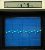
To test it, set the scope to 5v/div and 10uS/div and touch it to pin 5 of the TL594. You should see a signal like the one in the attached photo.
Are you sure that the scope is working properly?
To test it, set the scope to 5v/div and 10uS/div and touch it to pin 5 of the TL594. You should see a signal like the one in the attached photo.
Attachments
![100_2261 [Desktop Resolution].JPG](/community/data/attachments/139/139271-a318428e7c7e7cd6a0f769945ec7bd17.jpg)
![100_2262 [Desktop Resolution].JPG](/community/data/attachments/139/139279-7b43682b9f033551cda50a36e6360347.jpg)
- Status
- This old topic is closed. If you want to reopen this topic, contact a moderator using the "Report Post" button.
- Home
- General Interest
- Car Audio
- Two Noisy amps need repair.