Should I replace the MPSA06's and MPSA56's? I have them in stock.
Also I justed wanted to say that me and alot of other people really appreciate your time and expertise helping others.
I have learned so much from you just in the past few month's being a member of this forum. Again, Thank You!
Also I justed wanted to say that me and alot of other people really appreciate your time and expertise helping others.
I have learned so much from you just in the past few month's being a member of this forum. Again, Thank You!
No need to thank me.
Can you post the voltages again on the outputs. This time, place the black meter lead on the secondary center tap of the transformer for the channel you're measuring.
Leg 1 = Base
Leg 2 = Collector
Leg 3 = Emitter
2SB817
Base
Collector
Emitter
2SD1047
Base
Collector
Emitter
I wouldn't replace anything until we do more troubleshooting (unless you've removed the parts or know for a fact they're defective).
Perry Babin said:No need to thank me.
Can you post the voltages again on the outputs. This time, place the black meter lead on the secondary center tap of the transformer for the channel you're measuring.
Leg 1 = Base
Leg 2 = Collector
Leg 3 = Emitter
2SB817
Base 29.6
Collector 29.6
Emitter 30.2
2SD1047
Base - 30.3
Collector 29.6
Emitter - 30.3
I wouldn't replace anything until we do more troubleshooting (unless you've removed the parts or know for a fact they're defective).
Ok, I posted measurements above.
It appears that the 2sb817 is being driven on. Since the amp isn't drawing excessive current, the problem is probably in the preamp section.
If you follow the circuit back, you should find that the bases of the outputs go to the diver transistors (transistors with metal tabs). There is an op-amp near them (4562D?). Give me a list of the DC voltages on the 8 pins of the IC. Look up the datasheet (posted previously) for the pin configuration. Again, use the secondary center tap for the reference (black lead).
Pin 1:
Pin 2:
Pin 3:
Pin 4:
Pin 5:
Pin 6:
Pin 7:
Pin 8:
Perry Babin said:It appears that the 2sb817 is being driven on. Since the amp isn't drawing excessive current, the problem is probably in the preamp section.
If you follow the circuit back, you should find that the bases of the outputs go to the diver transistors (transistors with metal tabs). There is an op-amp near them (4562D?). Give me a list of the DC voltages on the 8 pins of the IC. Look up the datasheet (posted previously) for the pin configuration. Again, use the secondary center tap for the reference (black lead).
Pin 1:.12.8
Pin 2:.1.4
Pin 3:.13.1
Pin 4:.-13.2
Pin 5:.0
Pin 6:.12.1
Pin 7:.13.2
Pin 8:.12.8
Perry, there was no 4562D. The only 8 pin op amps are near the century's w/metal tab's that were getting hot when testing voltages.They are Burr brown opa134pa's one per channel. The measurements are above.
I'm concerned that the op-amp is not the correct one. The OPA134 is a single op-amp. The OPA2134 is a dual op-amp and what I'd expect to see. Unless this is a special amplifier (limited edition) or they changed the design recently, I'd expect to see a 2 channel op-amp in that location.
I wanted to know which pin (7 or 8) was connected to the positive regulated voltage. Pin 4 of the 14 pin op-amps is connected to the positive regulated supply.
Unless someone else can tell us what is supposed to be in that location, you will need to trace the circuit from pin 7 to see if it goes to the driver transistors or to the regulated power supply.
Perry Babin said:I'm concerned that the op-amp is not the correct one. The OPA134 is a single op-amp. The OPA2134 is a dual op-amp and what I'd expect to see. Unless this is a special amplifier (limited edition) or they changed the design recently, I'd expect to see a 2 channel op-amp in that location.
I wanted to know which pin (7 or 8) was connected to the positive regulated voltage. Pin 4 of the 14 pin op-amps is connected to the positive regulated supply.
Unless someone else can tell us what is supposed to be in that location, you will need to trace the circuit from pin 7 to see if it goes to the driver transistors or to the regulated power supply.
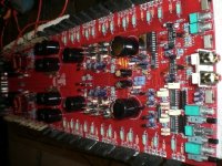
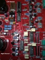
Ok I don't know if this answers your question but this board if you draw a line down the middle it would almost be a mirror image from left to right side, Their is a burr brown on both left and right channels or sides and they are a OPA134PA single amp chip.
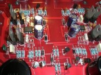
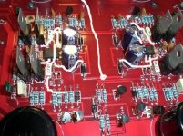
Now as far as tracing the #7 pin, It goes through a diode and from the diode it goes to a 2N6488 NPN 3rd leg that has been soldered to the underside of the board to be against the heat sink also trace divides and goes to 2 MPSA06's 3rd leg's. I hope this helped. heres some pic's
Attachments
")
Perry Babin said:Does pin 6 go to to the center of the 4 diodes in series?
If you are talking the same one's pin 7 goes to, no.
Pin 6 goes to a 2.7ohm resistor right next to it, Then goes to tiny glass diode which is in series to the one next to it then hits a trace that branches off 3 differn't ways. all stay in that little area. 1 goes across to the small white box capacitor and another goes to blue resistors and another to the mpsa06.
Anyway I traced a picture for you. Hope it helps.

Attachments
OP # 1 Pin voltages
4: 13.29
8: -.04
11: -13.36
12: .04
13: .05
14: .07
____________________________________________________
OP #2 Pin Voltages
same as above #1
____________________________________________________OP #3 Pin Voltages
1: .04 8: .04
2: .03 9: .04
3: .05 10: .04
4: 13.14 11: -13.32
5: .02 12: 0
6: .02 13: 0
7: .04 14: -.05
____________________________________________________
OP #4 Pin Voltages
1: .04 8: .05
2: .04 9: .05
3: .05 10: .05
4: 13.36 11: -13.13
5: .02 12: 0
6: .02 13: 0
7: .05 14 -.05
____________________________________________________
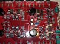
It took me awhile but here it is. In the top two OP's I left the 0 voltage pins out. Also I took a picture and numbered everything.
I wanted to tell you also the 2 Big blue resistors in the picture started to smoke after a couple of minutes being on testing and those century's got so hot you could smell them. Let me know what you think.
4: 13.29
8: -.04
11: -13.36
12: .04
13: .05
14: .07
____________________________________________________
OP #2 Pin Voltages
same as above #1
____________________________________________________OP #3 Pin Voltages
1: .04 8: .04
2: .03 9: .04
3: .05 10: .04
4: 13.14 11: -13.32
5: .02 12: 0
6: .02 13: 0
7: .04 14: -.05
____________________________________________________
OP #4 Pin Voltages
1: .04 8: .05
2: .04 9: .05
3: .05 10: .05
4: 13.36 11: -13.13
5: .02 12: 0
6: .02 13: 0
7: .05 14 -.05
____________________________________________________
It took me awhile but here it is. In the top two OP's I left the 0 voltage pins out. Also I took a picture and numbered everything.
I wanted to tell you also the 2 Big blue resistors in the picture started to smoke after a couple of minutes being on testing and those century's got so hot you could smell them. Let me know what you think.
Attachments

Email me the best photos you can get of the top and bottom of the board. Take two that cover the area of the 14 pin op-amps, two that cover the area of the regs (6488/91 under the board) and two that cover the area around the 134a (one each area from top and bottom). Send them at the highest resoultion. Please zip them.
babin_perry@yahoo.com
The voltage on the 14p op-amps looks OK. There must be a DC blocking cap in the board somewhere.
I posted a link for #6. It's not likely to be causing the problems here. #7 is a microcontroller. It doesn't do much. When the amp powers up, the IC sends a signal to the digital pot telling it to go to 'full volume'. After that, it doesn't do anything unless you use the remote level controller.
- Status
- This old topic is closed. If you want to reopen this topic, contact a moderator using the "Report Post" button.
- Home
- General Interest
- Car Audio
- Orion HCCA 275G4