

Homeskillet's House
of Audio Electric Oddities
of Audio Electric Oddities
The circuits shown here are most certainly not appropriate for general use. I build them for my own enjoyment and curiosity. They usually are dismantled in a few days and the parts are used for something else.
The schematics and designs here are all bench designed using a basic circuit idea and then trial and error to arrive at specific values. They may have problems.
They are connected to a variac with a fuse and current meter. They are turned on and off by slowly turning the variac up and down. They are not subject to any of the rigors of consumer use and they are not intended to be.
I always wear eye protection and turn the power off by turning down the variac. Nothing is subjected to hard switching or a quick turn on. I also work with one hand behind my back if the circuit is to be approached while powered on.
I also continually check to see if the power is truly off as I work on a circuit by verifying the variac is off and the voltmeter and current meter reads zero. It is easy to be interrupted and resume working on a circuit to find that you haven't powered it down so checking continually as one works helps prevent this.
I also power the unit down and let it drain before applying test leads or making any change whatsoever. This part is really a big deal.
If I do post anything that is a working design suitable for general use I'll make a note of it and probably make a big deal of it.
Variable output impedance tone control
Posted 6th August 2013 at 04:43 AM by homeskillet
Updated 28th August 2013 at 01:49 AM by homeskillet (It's a goofy idea and best left alone.)
Updated 28th August 2013 at 01:49 AM by homeskillet (It's a goofy idea and best left alone.)
Aug. 27th, 2013 edit:
Tapping the output transformer as a balanced secondary is totally goofy as was determined by Osvaldo de Banfield and Cnpope (Chris) here:
https://www.diyaudio.com/forums/tubes...madness-2.html
I'll leave it posted here just to show that I'll try just about anything and to show that it's unwise.
Aug. 7, 2013 edit:
I was just looking for the Hawksford and Mills current amp paper on google and I found this very blog post so I thought I would point out a potential drawback to the following feedback technique. Hawksford and Mills claim that using a sense resistor to the ground return from the speaker introduces a distortion similar to "interface distortion" in voltage amplifiers.
There is very little I could find about interface distortion.
As far as I can see it, this feedback scheme may introduce back emf from the speaker and feed it back to the amp which would add a distortion product to the amp and not necessarily reduce it.
That said, the effect of this feedback scheme was interesting and it wasn't a bad sounding amplifier. It was able to amplify solo piano passably where this has always been a problem with my other direct connected amps with no feedback.
Here follows the original blog post:
I read a paper by Hawksford and Mills concerning current drive for loudspeakers and they found a feedback scheme from the secondary of the output transformer raised the output impedance (which is what I was hoping for) but was dependent on frequency.
As far as I could understand this scheme gives a boost to the low frequencies but then gives continually lower output as the frequency increases. This is exactly what I found with my feedback scheme using one of the taps of the output transformer secondary as a speaker center tap and then sending that to the cathode of V1 here:
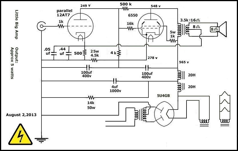
I included the small value bypass caps to the cathode resistor of V1 to offset this and bring the high frequencies up. The response is not "ruler flat" with the addition of the caps but it doesn't seem to vary much and then starts to dip past 20kHz to 40kHz.
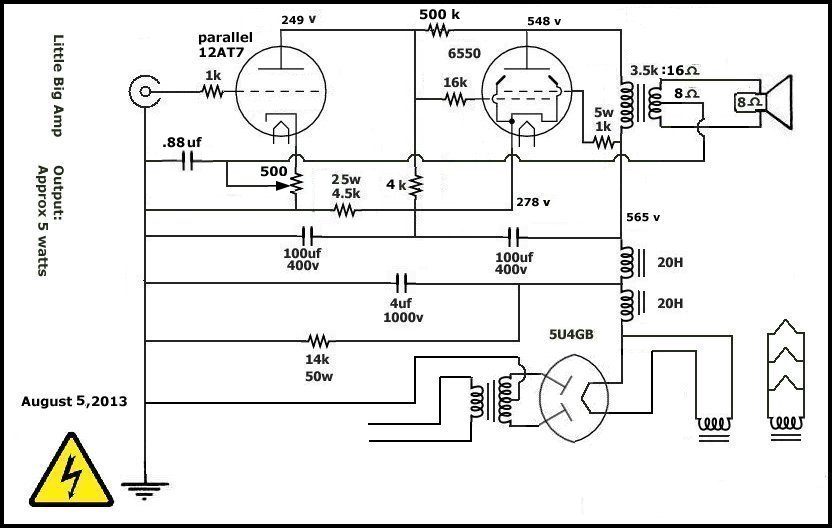
Mills and Hawksford found this to be less than optimal but then I saw an opportunity for a tone control. Since I had a pot serving as the cathode resistor of V1, I connected the bypass caps and the feedback return to the swiper and used the full 500 ohms as the cathode resistor which I was anyway.
This works quite nicely and doesn't sound too bad. I found I enjoy being able to set it where it "seems best".
I keep wanting to put this circuit away but it keeps drawing me back in.
Here it is with the new fangled "Variable Output Impedance Tone Control".
Tapping the output transformer as a balanced secondary is totally goofy as was determined by Osvaldo de Banfield and Cnpope (Chris) here:
https://www.diyaudio.com/forums/tubes...madness-2.html
I'll leave it posted here just to show that I'll try just about anything and to show that it's unwise.
Aug. 7, 2013 edit:
I was just looking for the Hawksford and Mills current amp paper on google and I found this very blog post so I thought I would point out a potential drawback to the following feedback technique. Hawksford and Mills claim that using a sense resistor to the ground return from the speaker introduces a distortion similar to "interface distortion" in voltage amplifiers.
There is very little I could find about interface distortion.
As far as I can see it, this feedback scheme may introduce back emf from the speaker and feed it back to the amp which would add a distortion product to the amp and not necessarily reduce it.
That said, the effect of this feedback scheme was interesting and it wasn't a bad sounding amplifier. It was able to amplify solo piano passably where this has always been a problem with my other direct connected amps with no feedback.
Here follows the original blog post:
I read a paper by Hawksford and Mills concerning current drive for loudspeakers and they found a feedback scheme from the secondary of the output transformer raised the output impedance (which is what I was hoping for) but was dependent on frequency.
As far as I could understand this scheme gives a boost to the low frequencies but then gives continually lower output as the frequency increases. This is exactly what I found with my feedback scheme using one of the taps of the output transformer secondary as a speaker center tap and then sending that to the cathode of V1 here:
I included the small value bypass caps to the cathode resistor of V1 to offset this and bring the high frequencies up. The response is not "ruler flat" with the addition of the caps but it doesn't seem to vary much and then starts to dip past 20kHz to 40kHz.
Mills and Hawksford found this to be less than optimal but then I saw an opportunity for a tone control. Since I had a pot serving as the cathode resistor of V1, I connected the bypass caps and the feedback return to the swiper and used the full 500 ohms as the cathode resistor which I was anyway.
This works quite nicely and doesn't sound too bad. I found I enjoy being able to set it where it "seems best".
I keep wanting to put this circuit away but it keeps drawing me back in.
Here it is with the new fangled "Variable Output Impedance Tone Control".
Total Comments 0

