


GB F5 Guide (pcb version 2)
As promised, I would make a guide to the boards and in particular to the additions I have made to the F5. I decided to do this in the blog, because then you can give me comments which I can use for improving the doc. However I'm not done at all, but I thought it would be nice to give you access to the BOM I have made.
IMPORTANT: Before you start stuffing your boards, you must read the manual/article written by Nelson Pass available for download on the First Watt website (First Watt: Products: F5).
Detailed guide by Steve and Matt: https://www.diyaudio.com/forums/pass-...mentation.html
PCB
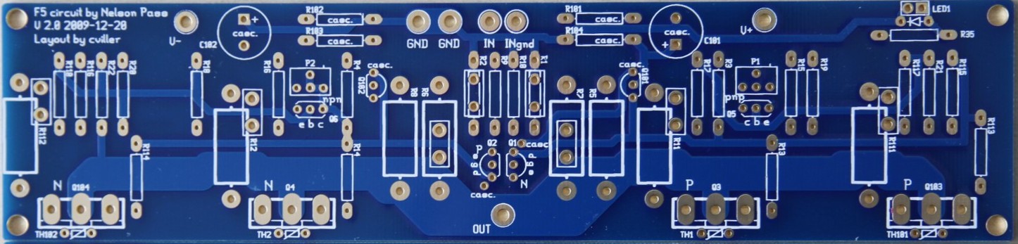
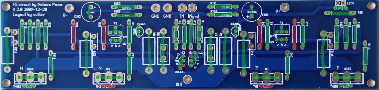
Here is a picture of the pcb.
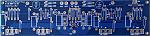
There are no more boards available, but you can order F5 boards on the diyAudio store.
Schematics
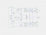
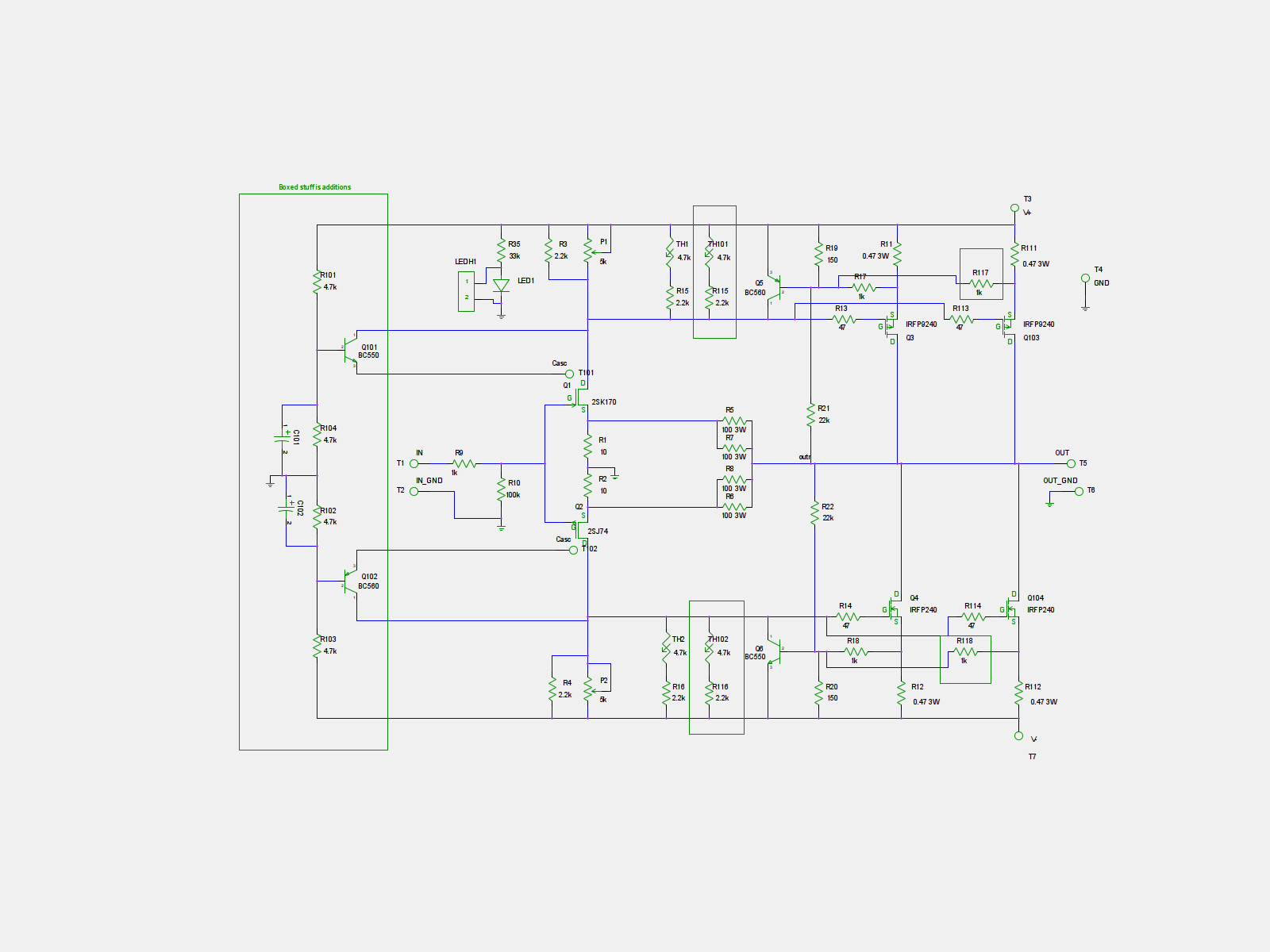
Optionality
With the addition of optional extra output mosfets and cascoding, there are many possible ways to build the amp. Here I'll try to explain some of them.
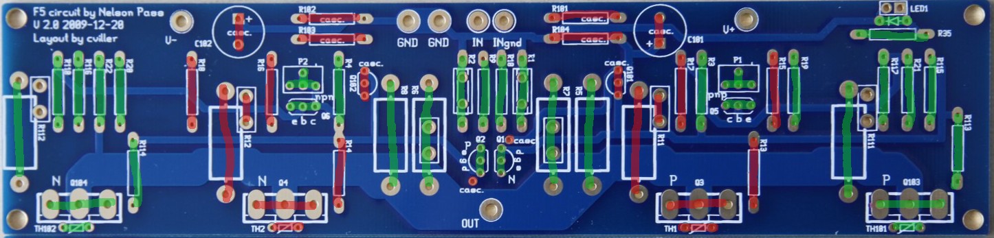
Stock F5 example
Greens are populated and reds are left open.
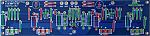
Here I have used the outputs farthest apart and notice I have also used the corresponding thermistor and sensing resistors.
Double Ouput Mosfets
Greens are populated and reds are left open.
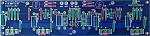
When the other output device is populated, you should not add extra thermistors, but you can chose if you want to use the inner our outer mosfet as reference - I have chosen the outer.
The output fets must be matched in pairs - the two N's should have same vgs and the P's must have same vgs.
The extra output devices will allow you to run the amp at higher currents, which is good for driving low impedance speakers. But be sure to have a large enough heatsink if you chose to crank up the bias.
Cascode and Double Output
Greens are populated and reds are left open.
The cascoded option with double outputs requires two extra transistors and the voltage dividers. Notice that one of the legs of both jfets has to be bend slightly to connect to the hole designated "casc.".
The cascoded option is mainly there to allow for slightly higher supply voltages. Doing the cascode does require some electronics skills, because you may need to adjust some values to get the required headroom for operations. You can read more about cascodes in Nelson Pass' excellent article on the topic: https://www.passdiy.com/pdf/articles/cascode.pdf
BOM
bom.pdf
Output devices
You can use many different output devices for this amp, but the standard is Fairchilds FQA19N20C and FQA12P20C. They can be difficult to get your hands on, so you can use the IRFP parts instead.
Sourcing components
You can order component kits from various diyAudio members.
North America
jackinnj: Tech DIY Company Store (many full clone kits)
Europe
h_a: F5 amp transistor kits
FAQ
Increasing the feedback resistor will lower the amount of feedback, so you'll get more gain and distortion.
I use 14-16 gauge wire for the PSU and outputs and shielded wires for the input. I don't think this is the place where you will see the most improvement from exotic parts, but don't use crummy wire either.
You can use double outputs to lower the load on each mosfet or increase the total bias. If you increase the bias to twice the stock value, then your heatsink needs to dissipate twice as much heat.
With the stock F5, you are dissipating around 60 watt per channel, so you need a 0.3C/W sink to stay below 20C over ambient temperature.
With the double amount of dissipation, your sinks need to be 0.15C/W per channel.
IMPORTANT: Before you start stuffing your boards, you must read the manual/article written by Nelson Pass available for download on the First Watt website (First Watt: Products: F5).
Detailed guide by Steve and Matt: https://www.diyaudio.com/forums/pass-...mentation.html
PCB
Here is a picture of the pcb.
There are no more boards available, but you can order F5 boards on the diyAudio store.
Schematics
Optionality
With the addition of optional extra output mosfets and cascoding, there are many possible ways to build the amp. Here I'll try to explain some of them.
Stock F5 example
Greens are populated and reds are left open.
Here I have used the outputs farthest apart and notice I have also used the corresponding thermistor and sensing resistors.
Double Ouput Mosfets
Greens are populated and reds are left open.

When the other output device is populated, you should not add extra thermistors, but you can chose if you want to use the inner our outer mosfet as reference - I have chosen the outer.
The output fets must be matched in pairs - the two N's should have same vgs and the P's must have same vgs.
The extra output devices will allow you to run the amp at higher currents, which is good for driving low impedance speakers. But be sure to have a large enough heatsink if you chose to crank up the bias.
Cascode and Double Output
Greens are populated and reds are left open.
The cascoded option with double outputs requires two extra transistors and the voltage dividers. Notice that one of the legs of both jfets has to be bend slightly to connect to the hole designated "casc.".
The cascoded option is mainly there to allow for slightly higher supply voltages. Doing the cascode does require some electronics skills, because you may need to adjust some values to get the required headroom for operations. You can read more about cascodes in Nelson Pass' excellent article on the topic: https://www.passdiy.com/pdf/articles/cascode.pdf
BOM
bom.pdf
Output devices
You can use many different output devices for this amp, but the standard is Fairchilds FQA19N20C and FQA12P20C. They can be difficult to get your hands on, so you can use the IRFP parts instead.
Sourcing components
You can order component kits from various diyAudio members.
North America
jackinnj: Tech DIY Company Store (many full clone kits)
Europe
h_a: F5 amp transistor kits
FAQ
Quote:
What happen in F5 if I use 60 or 75 ohm in place of 50 one ?
Quote:
What cables do you use?
Quote:
Could you give more information about possible changes in bias and other settings for double mosfet option comparing to stock. What are your recommendations for the power supply/transformer and heat sinks?
With the stock F5, you are dissipating around 60 watt per channel, so you need a 0.3C/W sink to stay below 20C over ambient temperature.
With the double amount of dissipation, your sinks need to be 0.15C/W per channel.
Quote:
Thanks to AudioSan for this guidance to cascode calculation:
Rail voltage divided by (R103+R102) multiplied by R102 = coscoded voltage.
so f.ex: 35V rails / (4.75K+4.75K) x 4.75K= 17.5V to the J-fets. to get higher voltage for the J-fets, just increase R102 and/or decrease R103. and the other way around to lower the voltage.
the caps can be around 10uF. not very important
Total Comments 98
Comments
-


Quote Me: "Cool"
This is a much better method to compile pertinent information about 'builds' using your boards than you've used in the past. Cool!
Thanks
CharlesPosted 4th February 2010 at 09:11 PM by cowboy99

-
 Thanks. I'll do the same for F4 and perhaps one about how to wire a psu.Posted 4th February 2010 at 10:17 PM by cviller
-
CV,
I did not see the parts list for the additional parts to do the cascode mod ?
regardsPosted 5th February 2010 at 05:31 AM by a.wayne
-
OK , Found it .......
 Posted 5th February 2010 at 05:32 AM by a.wayne
-
cv
can you give a brief comparison of the different options, power output differences, etc?
thanks
-joePosted 12th February 2010 at 11:54 AM by jtktam
-
In the Stock F5 picture, any reason why Q101 isn't marked?
Thanks.
Anand.Posted 17th February 2010 at 07:06 PM by nycavsr2000
-
No, I just noticed that today. It should not be populated in the stock version. Thanks for spotting it, I'll update it later.
To joe, I wrote some more about the outputs - does it answer your question?Posted 17th February 2010 at 07:15 PM by cviller
-
cv
it helps a bit.. for my larger tower speakers running at 4ohms it's probably better to do a two output pair?
i am going to read up on the cascode
GREAT WORK on the pcb btw
-joePosted 20th February 2010 at 02:50 PM by jtktam
-
Thanks!
The stock F5 will probably run your speakers just fine, but you'll get less distortion at high volumes with more bias current.Posted 20th February 2010 at 04:10 PM by cviller
-
Can you give us a basic guide on the configuration of the cascode?Posted 22nd February 2010 at 11:51 AM by derwhalfisch
-
+1Quote:Can you give us a basic guide on the configuration of the cascode?
in the BOM it says the resistor values might need to change.. how do we determine what values to use?
-joePosted 22nd February 2010 at 07:38 PM by jtktam
-
Hi Christian,
I'm using your version1 board. I have a question to ask:
I connect the speaker ground post directly to the PSU ground plain instead of connect it to the ground point on the amp PCB, is it OK or not?
ThanksPosted 25th February 2010 at 07:27 AM by ncc
-
I have not had time to build a cascode version yet, so the things I can say about it will be general guidelines. But I'll try to write something about it - however probably not right now since I'm quite busy.
Bjarne, you can order some boards from me if you like - just read the PCB section of this blog.
ncc, that is ok, but if you experience hum, then you might want to change it. I have not tried doing it that way, so I can't be very specific - please report back about your findings.Posted 25th February 2010 at 03:25 PM by cviller
-
 NCC,
NCC,
From my experience in destroying these beautiful boards I have found when I isolated both the signal and speaker grounds (binding posts / RCA jacks) running the wires directly to and from CV's boards the amp is DEAD QUIET. I can't tell its on it's so quiet. Why chance it?
RonPosted 8th March 2010 at 11:10 PM by Renron
-
Cvillier,
I would like to run more than the 2 pr allowed per board , what would be your suggestion.
1. Use 2 boards per side , can they be parallel for 8 outputs /ch .
2. hard wire them in
3. will there be a source resistor issue ?
4. Is this even possible without driver stage ?
regards ,Posted 9th March 2010 at 06:02 AM by a.wayne
-
I'm not sure the jfets will like to drive that many devices, but if you want to do it, the easiest solution would probably be to wire them or have a secondary board with only output fets, source resistors and gate stoppers.Posted 9th March 2010 at 06:12 AM by cviller
-
Hello Cviller,
Yes this is what i had thought about doing , using the xtra boards for the xtra outputs with there source resistors , what is the gate stoppers ? where are they located on the board ?
regards,Posted 9th March 2010 at 06:30 PM by a.wayne
-
Gate stoppers are those 47ohm resistors located very close to the gates of the mosfets - they prevent oscillations.Posted 9th March 2010 at 06:31 PM by cviller
-
Hello Cvilliers,
Is it possible if you could put up a pic of the board as you currently have at the top now showing what to use /not to use , jumpers placement and wired connections if necessary to incorporate both boards.
regards,Posted 9th March 2010 at 11:10 PM by a.wayne
-
Hi a.wayne.
That was the purpose of the pictures below the schematics. Green is with components and red is left open.Posted 14th March 2010 at 02:50 PM by cviller

