Hi Peter
Is it possible to buy some of the parts for the DAC from you? Not the entire kit but some of the ICs.
Another thing, I thought that I should use a single 12V transformer which are on sale at my local electronicsshop but I'm not sure about the VA-rating, how low can I go?
Kind regards
Ken
Is it possible to buy some of the parts for the DAC from you? Not the entire kit but some of the ICs.
Another thing, I thought that I should use a single 12V transformer which are on sale at my local electronicsshop but I'm not sure about the VA-rating, how low can I go?
Kind regards
Ken
Peter Daniel said:The difference between dual mono and stereo is the number of rectifier boards used in powering the amp. In stereo, both channels are powered from the same board, in dual mono each channel has its own separate board.
While in stereo setups with a single transformer you could still use two separate boards, on more than one occasion I had reports of humming supply so I always recommend using a single rectifier board.
That's also what I'm doing in all my stereo amps and in the picture below I'm showing trouble free way to connect power grounds: output grounds of both channels (OG) are connected with a piece of thick copper wire. Central point on that wire is power star ground and all 4 ground wires from rectifiers board (PG+, PG+ and PG-, PG-) are connected here. Output grounds are taken directly from the board, signal ground connects to the point on the board marked as SG.
Those boards were designed with dual mono operation in mind and as such they work well without any mods.
I finished assembling my parallel lm4780 kit a few days ago, and am having a terrible humming problem. When only one channel is hooked up it is nearly completely silent (I can only hear a small noise when my ear is right next to the speaker). When I hook both channels up to the same transformer I get a terrible hum.
I have a few questions on the subject...
1. You said that you recommend only using a single rectifier board, is a single board sufficient to power two parallel 4780's?
2. From what I can see a solution would be to connect all of my ground points like in the quoted post above. Do the PG+/- have to be connected to the amp boards? It does not look like they are in the above picture. Also, is it fine if they ARE connected and I connect all the points to try to solve my humming problem?
phatcenter77 said:1. You said that you recommend only using a single rectifier board, is a single board sufficient to power two parallel 4780's?
2. From what I can see a solution would be to connect all of my ground points like in the quoted post above. Do the PG+/- have to be connected to the amp boards? It does not look like they are in the above picture. Also, is it fine if they ARE connected and I connect all the points to try to solve my humming problem?
In most cases a single rectifier board should be sufficient for two parallel LM4780; I've been using such configuration and it worked well. You may check the temp of rectifiers, if they run too hot use some heatsinking (isolation pads are required if diodes are mounted to a common heatsink)
In a pictured exampled, the output grounds of both channels are connected with a thick copper wire and all grounds from rectifiers boards (PG+/PG-) are connected to a central poin there (and they need to be connected).
More info on wiring amp kits has been posted here:
http://www.diyaudio.com/forums/showthread.php?postid=1108820#post1108820
http://www.diyaudio.com/forums/showthread.php?postid=787773#post787773
phatcenter77 said:Also, can all these points be connected directly to mains ground? It looks like you have a resistor before mains ground...
Those points are connected directly to the chassis, and they can be also connected directly to mains ground, although I'm using 10R resistor to separate chassis ground from mains ground.
I cannot recomment Peter higher. I am a noob to this and his emails have been FAST and all my questions answered. Helped me get a nice order going! Thanks man, rare to come across a business that actually gives a crap about there customer during and after payment is made! Cannot wait to get these new toys singing!
NOS DAC Premium Kit
Peter,
I have built the Premium NOS DAC kit and it has been running for about 5 hours. Reading peoples comments about this DAC did not prepare me for how it sounds in my system. It is the first time in using a digital source that I start to hear what I get from vinyl - and that is saying something!
My digital front end is QNAP TS101 320GB NAS feeding into a Squeezebox (SB3); after the DAC is a Promitheus TVC followed at the moment by an LM3875 Basic kit Gainclone (I did initially use the LM3886 but quickly changed to the 3875) into Spendor BC1s.
I am really looking forward to getting my Linkwitz Orions running with a set of gainclone amps but for the moment I am happy to listen to the system as it is and to hear how the DAC settles in.
Many Thanks
Alan
")
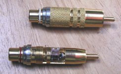
Andrew Rothwell does some good in line attenuators. They also can make them to suit the attenuation you require.
http://www.rothwellaudioproducts.co.uk/html/inline_attenuators.html
http://www.rothwellaudioproducts.co.uk/html/inline_attenuators.html
Aargh ! DAC not working !
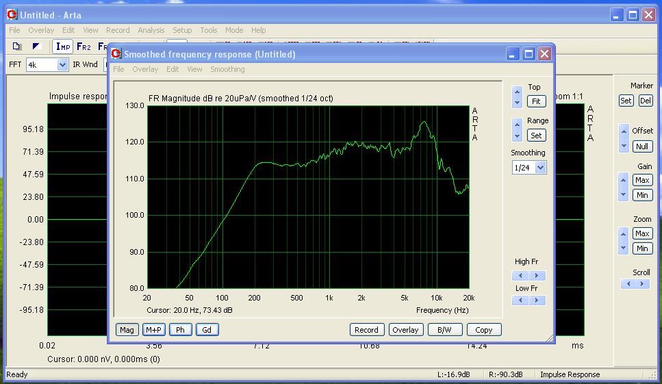
I finally started testing the DAC, but it's not making any music !!!
I started the tedious task of measuring the voltages on each of the ICs, and here are my results :
The only thing that doesn't seem right, is that on the schematic, pin 5 and 6 on the receiver got to pin 10 and 9 (respectively) is the CS8412, but on the board I've got, they go to 9 and 10 ...
There are no shorts on the SMD components, and I get 4V before the output capacitors (am using 0.47uF), and get 0V DC after.
Code:
[b]SN75179[/b]      [b]TDA1543[/b]
1: [b]5V        8V[/b]
2: [b]4.5V      2V[/b]
3: [b]4.5V      2V[/b]
4: [b]0V        0V[/b]
5: [b]5V        8V[/b]
6: [b]0.5V      4V[/b]
7: [b]2.3V      2V[/b]
8: [b]2.3V      4V[/b]

[b]CS8412[/b]
1-3 : [b]2V[/b]
4-7 : [b]7V[/b]
8 :   [b]2V[/b]
9 :   [b]5V[/b]
10 :  [b]0.5V[/b]
11 : [b]2V[/b]
12 : [b]7V[/b]
13 : [b]0V[/b]
14 : [b]2V[/b]
15 : [b]7V[/b]
16 - 19 : [b]0V[/b]
20 : [b]2V[/b]
21 : [b]0V[/b]
22 : [b]5V[/b]
23 : [b]0V[/b]
24 - 25 : [b]7V[/b]
26 - 27 : [b]2V[/b]
28 : [b]7V[/b]OK, found the problem (silly me).
Earlier I put a capacitor in the wrong place. Removing it left some solder closing the hole, which couldn't be removed, so I "scraped" it away, and put the correct cap in.
Now I realised that all that "scraping" removed the copper that joined the ground from top of the board to bottom. A wire jumper now connects the grounds, and the DAC is finally making music !
Albeit everything is connected with aligator clips ...
Sorry for spamming the board !
- Status
- This old topic is closed. If you want to reopen this topic, contact a moderator using the "Report Post" button.
- Home
- More Vendors...
- Audio Sector
- AudioSector-chip amp kits, dacs, chassis