If your speaker are 96db / Watt / meter then I think u can more or less choose what ever voltage sounds best !
Unless you listen at VERY high levels it is unlikely you will that you will ever get to higher that 20watts in the range that may be 6 ohms
It is more usual for the highest power to be in the deep bass where u sensibly speculate that the impedance rises.
since Peter says the higher voltage sounds better I would for for that.
+ / - 35 would get my vote
that's my half penny worth
")
Unless you listen at VERY high levels it is unlikely you will that you will ever get to higher that 20watts in the range that may be 6 ohms
It is more usual for the highest power to be in the deep bass where u sensibly speculate that the impedance rises.
since Peter says the higher voltage sounds better I would for for that.
+ / - 35 would get my vote
that's my half penny worth
phatcenter77 said:I need just one power supply board, and related parts. If I need to order a complete PCB set that's fine.
I will send you replacement rectifier board free of charge, You will also need 8 diodes and two caps, that would be $10 including shipping, e-mail me for payment info.
Re: Transformer selection; interaction between speaker impedence/supply voltage/power out
I wouldn't be much concerned with those graphs published by National. I once tested the amp into a dummy load, and IIRC even for 4ohm load and 34V supply rails I was getting some 36W output power.
I also tested the amp connected to variac where I could change PS voltage and compare how it affects sonic signature. With lower voltage the sound is smoother and more laid back, with higher supply it becomes more "alive" and dynamic, with better presence and involvement factor. It may be a matter of personal preferrence, but my choice goes to higher voltages. Even when I was running GC from batteries with 6ohm speakers I opted for 3 x 12V cells per rail and supply voltage close to 40V DC.
Presently, I choose 2 x 22V secondries on Plitron transformers I'm using. This produces close to 34V DC rails, with 2 x 24VAC secondaries the actual DC voltage would be 37V DC ( taking into account regulation margin and usually higher mains level).
300VA is not really an overkill, considering that Naim uses 800VA for preamps
I wouldn't go with less than 220VA though. The lower power transformer may sound a bit lean, higher power units may be a bit edgy, although good dynamically. I'm using 300VA units in both stereo and monoblock versions and find them as good compromise.
autopoiesis said:He posted previously that the higher the rail voltage, the better the amp sounds. My speakers are nominally 8 Ohm, 96db/1W, two-way passive. Although I don't have a Z-curve to see how far Z varies, I am aware that it could be well below 8 Ohms in places.
Page 10 of the datasheet for the LM3875 (http://www.national.com/ds.cgi/LM/LM3875.pdf) shows the attached graph of output power vs supply voltage, for R=4,6 and 8 Ohms, but for a purely resistive load.
Now, 2x25V transformer will give ~±35V rail voltage (1.4 x Va, minus diode losses I put at zero).
Let's assume that Z drops to 6 Ohms from, say, 300-1000Hz, but is higher elsewhere - leading to the nominal 8 Ohm rating.
With rail voltage at 35V, one infers from the R=6 Ohm curve that the chip could supply only 20W at those frequencies, but nearly 60W at frequencies where Z was 8 Ohms.
I don't fully understand the interactions between these variables or whether this inference is well founded. (Or if I should be concerned at all - no-one seems to experience this
And finally, is 300VA overkill for dual monoblocks? My speakers roll off quite high and I have an active mono sub (which won't be powered by a GC, for now). I'm looking for dynamics/detail with the GCs and understand that a lower VA transformer might be more apt if weighty bass is less of any issue...
I wouldn't be much concerned with those graphs published by National. I once tested the amp into a dummy load, and IIRC even for 4ohm load and 34V supply rails I was getting some 36W output power.
I also tested the amp connected to variac where I could change PS voltage and compare how it affects sonic signature. With lower voltage the sound is smoother and more laid back, with higher supply it becomes more "alive" and dynamic, with better presence and involvement factor. It may be a matter of personal preferrence, but my choice goes to higher voltages. Even when I was running GC from batteries with 6ohm speakers I opted for 3 x 12V cells per rail and supply voltage close to 40V DC.
Presently, I choose 2 x 22V secondries on Plitron transformers I'm using. This produces close to 34V DC rails, with 2 x 24VAC secondaries the actual DC voltage would be 37V DC ( taking into account regulation margin and usually higher mains level).
300VA is not really an overkill, considering that Naim uses 800VA for preamps
I wouldn't go with less than 220VA though. The lower power transformer may sound a bit lean, higher power units may be a bit edgy, although good dynamically. I'm using 300VA units in both stereo and monoblock versions and find them as good compromise.
I hope it is okey that I ask this question here.
I have just finished building my Lm4780 and I really like the sound so far. But, one of the Lm4780 gets much warmer than the other one when I'm playing music.
Edit : It also happens when there are no speakers and input devices conected. Is it called idle?
But, even here one of the Lm4780 gets much warmer than the other one. However, I think both Lm4780 gets a little bit too warm.
What could be the problem?
/ fredrik
Im running them as parallel.
I noticed one thing when I made som measurments. When I measured the resistance on the speaker-out contacts ( with nothing connected to it) I get two different values.
The coolest ship had 40 R and the warmer one got 135 R.
Perhaps it is a resistor with wrong value?
Should I try too measure with an oscilloscope to se if there are any oscillations?
I feel like a real beginner right now! =)
Disconnect output 0.1R resistors (R8 and R9) from /OUT/ connection and measure the DC offset from each half of the chip separately for both chips.
http://www.audiosector.com/lm4780 amp.pdf
http://www.audiosector.com/lm4780 amp.pdf
Man this all looks great guys! I did not know anything about chip amps / do not know much about building amps in general and reading through all of this is very exciting. I dig projects and want to give props to people like Peter making these things a reality for us DIY types. Thanks man!
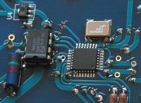
I received some enquiries with regards how to mount crystal oscillator in USB DAC: the pads went over footprint overlay and it's not clear what is pin #1. So I mark each board by engraving a small dot next to pin 1 (on the oscillator).
Below is the pic showing proper footprint.
Below is the pic showing proper footprint.
Attachments
The oscillator can be sourced from Mouser: http://www.mouser.com/search/refine.aspx?Ntt=549-C3391-12.000
Attachments
Re: Re: Transformer selection
Peter,
Thank you for your response.
Just one thing: how to calculate the regulated voltage?
I had thought that the rectified and smoothed voltage would be the RMS the peak to peak, (x0.707 IIRC), doubled up for + and - supplies (previous post).
That's where I got the rough estimate 1.4 x VAC, and the figure of 25V secondaries for 35V rails.
You say 2x24VAC => ~37V DC, but I make it 34VDC.
I'm sure you're right, but how do you do the calculation? What is a usual margin for 'usually higher mains level'. Mine (nominally 230V) reads *exactly* 230V.
Now that my LM3875 kit is in the post (thank you), I'm on the point of ordering the transformers. I was going to go for 2X25V, but now I'm not so sure...
Best wishes to all,
Steve
Peter Daniel said:
Presently, I choose 2 x 22V secondries on Plitron transformers I'm using. This produces close to 34V DC rails, with 2 x 24VAC secondaries the actual DC voltage would be 37V DC ( taking into account regulation margin and usually higher mains level).
Peter,
Thank you for your response.
Just one thing: how to calculate the regulated voltage?
I had thought that the rectified and smoothed voltage would be the RMS the peak to peak, (x0.707 IIRC), doubled up for + and - supplies (previous post).
That's where I got the rough estimate 1.4 x VAC, and the figure of 25V secondaries for 35V rails.
You say 2x24VAC => ~37V DC, but I make it 34VDC.
I'm sure you're right, but how do you do the calculation? What is a usual margin for 'usually higher mains level'. Mine (nominally 230V) reads *exactly* 230V.
Now that my LM3875 kit is in the post (thank you), I'm on the point of ordering the transformers. I was going to go for 2X25V, but now I'm not so sure...
Best wishes to all,
Steve
Peter I'm wondering about MSR860s. e.g., d1-d4: it looks like on the s chematic and the pics you posted are at odds. looks like d1's anode, pin 3, should be connected to the transformer, but that doesn't look to be the case in the photo you posted earlier. Did anything change from earlier photos? thanks
Greg
Greg
gjash said:Peter, would there be any benefits to using a tentlabs oscillator? the package is different but I guess i could just solder the leads to the pads on your pcb....
There is enough space to fit Tent clock in top layer. Just drill 4 additional holes for the pins and wire them to the pads of the original oscillator. It's hard for me to comment on a difference, as I didn't try Tent clock here.
gjash said:Peter I'm wondering about MSR860s. e.g., d1-d4: it looks like on the s chematic and the pics you posted are at odds. looks like d1's anode, pin 3, should be connected to the transformer, but that doesn't look to be the case in the photo you posted earlier. Did anything change from earlier photos? thanks
The rectifier boards for LM3875 and LM4780 have diodes mounted in opposite way to match the opposite rail connection, see attached pic.
Attachments

Attachments
sorry not real all post in here
hii Peter
sorry not to read all your post in this thread
im afraid i will sleep in front of my computer LCD
178 page ... wow
maybe you must talk to moderator to split this
posting into 3 thread
Oh yes you are very famous in Indonesia and
and
i know for sure you never come here yet
i will tell this dac to my friend, byee
hii Peter
sorry not to read all your post in this thread
im afraid i will sleep in front of my computer LCD
178 page ... wow
maybe you must talk to moderator to split this
posting into 3 thread
Oh yes you are very famous in Indonesia
andi know for sure you never come here yet
i will tell this dac to my friend, byee
- Status
- This old topic is closed. If you want to reopen this topic, contact a moderator using the "Report Post" button.
- Home
- More Vendors...
- Audio Sector
- AudioSector-chip amp kits, dacs, chassis