Re: Balanced to unbalanced.
Better still, go and look at all the PASS balanced designs. Can any of them be copied with B1 components? Or be nice and ask on the PASS section. Nelson might be nice back and post the schematic you need.
use two B1s that are accurately matched , balanced needs better than 0.1% matching of all the sending and receiving resistors. If you can get 0.005% matching then do that.You also need to match the coupling and grounding capacitors, try for 0.5% matching.AlanElsdon said:My soundcard has balanced/unbalanced outputs, I will be building the Pass B1 buffer pre-amp (thanks for that info) and I would like to run the balanced output to the B1 -
Better still, go and look at all the PASS balanced designs. Can any of them be copied with B1 components? Or be nice and ask on the PASS section. Nelson might be nice back and post the schematic you need.
Hey Peter.
Im planning on ordering one of your LM3875 kits and I was wondering where (if) there was a good place in Canada to get the transformer. Digikey seemed to only have extreme transfos over 100$ and mostly non-stocked.
The other question, I bet its been asked before, if Im using a single transformer with one PSU board can I build on regular and one snubber? You dont need two for snubber do you?
(sorry, a n00b to chip amps)
btw my speakers are Rega Camber 1.5, 8ohm.
Thanks!
Best place in Canada for transformers: www.plitron.com
You can implement snubber with a single PS board.
You can implement snubber with a single PS board.
USB DAC Buffer Stage
Hi Peter!
I managed to went through all the pages of this informative thread, which took me a few sleepless nights...
But there is one thing I still don't understand, regarding your DAC's (USB and S/PDIF) and the use of a buffer stage, like the Burson or the B1 Jfet buffer:
IF such a buffer stages lowers the rather high output impedance of the DAC's output stage, and IF such a low output impedance is desired by most following stages (amps, pots, whatever), and IF such buffer is also benificial in cases when it's not even exactly needed (but didn't harm, though), WHY isn't such a buffer stage implemented in every DAC's output stage by default??
I mean, it would be quite easy to incorporate, say, the basic components of a B1 buffer into the circuit and pcb layout of your DAC's output stage, sharing the DAC's power supply, and make things a lot easier this way.
I'd like to read your comment about that.
Thanks!
Martin
Re: USB DAC Buffer Stage
Lets put it this way: all my offerings are direct byproducts of what I'm using myelf. If I don't need a buffer, I don't offer it with my products.
OTOH, the buffer is not realy needed. I only mentioned buffer to be applied with V-Caps, not because it "improves" the sound of a DAC: in fact, it does not.
The teflon V-Caps are pretty good caps, but also very expensive. To use them with a DAC in usual way, you would need values of 1-2uF and it would cost you $400-500 just for a pair of caps. Considering that sound improvement is probably no more than 10% comparing to BG N (in that particular circuit), it is not wise to use those caps. However, when you consider that 0.1uF V-Caps are "only" $100/pair, they suddenly become more realistic and within reach. And that's where buffer comes in: to allow the use of a DAC with low value coupling caps. But again, considering sonic improvement of less than 10% in comparison to standard application, it may not be everybody's cap of tea.
For instance, in my main system I use 0.1uF V-Caps, but still without buffer as 100k input impedance of my amp is not a problem with low frequency cut off.
In my office system, I use standard USB DAC with BG N and no buffer, and it still produces very enjoyable sound.
For the record, I never actually tried the buffer, I don't even know how it sounds")
martinbls said:IF such a buffer stages lowers the rather high output impedance of the DAC's output stage, and IF such a low output impedance is desired by most following stages (amps, pots, whatever), and IF such buffer is also benificial in cases when it's not even exactly needed (but didn't harm, though), WHY isn't such a buffer stage implemented in every DAC's output stage by default??
I mean, it would be quite easy to incorporate, say, the basic components of a B1 buffer into the circuit and pcb layout of your DAC's output stage, sharing the DAC's power supply, and make things a lot easier this way.
Lets put it this way: all my offerings are direct byproducts of what I'm using myelf. If I don't need a buffer, I don't offer it with my products.
OTOH, the buffer is not realy needed. I only mentioned buffer to be applied with V-Caps, not because it "improves" the sound of a DAC: in fact, it does not.
The teflon V-Caps are pretty good caps, but also very expensive. To use them with a DAC in usual way, you would need values of 1-2uF and it would cost you $400-500 just for a pair of caps. Considering that sound improvement is probably no more than 10% comparing to BG N (in that particular circuit), it is not wise to use those caps. However, when you consider that 0.1uF V-Caps are "only" $100/pair, they suddenly become more realistic and within reach. And that's where buffer comes in: to allow the use of a DAC with low value coupling caps. But again, considering sonic improvement of less than 10% in comparison to standard application, it may not be everybody's cap of tea.
For instance, in my main system I use 0.1uF V-Caps, but still without buffer as 100k input impedance of my amp is not a problem with low frequency cut off.
In my office system, I use standard USB DAC with BG N and no buffer, and it still produces very enjoyable sound.
For the record, I never actually tried the buffer, I don't even know how it sounds
Ah, ok - this clears things up. I thought a buffer would be beneficial in most applications, because if someone drives a power amp directly with the source device, this source should always have a low output impedance for best results (in case the power amp has, say, between 15k and 25k input impedance).
But then, if a buffer is not really needed, we should go without it, I would agree with this.
Thanks!
Martin
But then, if a buffer is not really needed, we should go without it, I would agree with this.
Thanks!
Martin
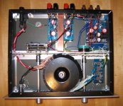
Another successful AudioSector project. I've had my LM3875 amp for a few years now. After I built my F3, it was just sitting there and begging for a new home. I purchased one of Peter's USBDACs and decided to combine the two (copying the master as he had done previously). I put in a pot while I was at it to make it a true integrated for my office system.
Thanks Peter!
Thanks Peter!
Attachments
Another 3875 amp & USB DAC
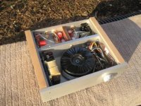
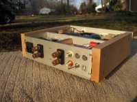
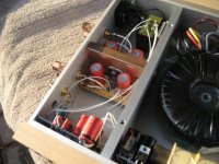
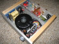
As long as we're showing off our handiwork, here's my latest gainclone, built using most of Peter's parts and grounding recommendations, along with an integral USB DAC. Details and lots of higher rez photos here:
http://mpbarneyamps.googlepages.com/gaincard-usbdac
This setup sound great, and along with a PC based music server, I'm listening quite a bit more now.
Thanks very much to Peter who's been very generous sharing his knowledge and techniques!
Mike
Attachments
Hi Peter! I have three more questions on your USB DAC please:
1) What is the total hight of the DAC (I mean from the bottom of the pcb to the top of the largest cap, regardless of the transformer) in mm?
2) I want to use a different transformer. What is the range of the ac input voltage I can use? You use a trans with 2x8V secondaries, would something up to 2x12V also be ok, or would this cause an overheating of some voltage regulators?
3) When I use your USB DAC and your LM3875 Basic Kit (with BG 4,7/50 input cap), which would be the better value for a volume pot, 25k or 50k (I have both lying around)?
Thanks!
martin
Assembled DAC board on 1/4 standoffs fits inside standard (1/8 x 2 x 3") aluminum tubing. So the dimension you are looking for is approx 65mm.
I'm using 2 x 8V AC transformers, and 2 x 9 is probably more common. Never tried with 2 x 12V and DAC chip 8V regulator might run a bit hot, but I don't think it would be really critical. You can always increase the value of series resistors (20R gives 1V drop in my setup)
I would go for 25k pot.
I'm using 2 x 8V AC transformers, and 2 x 9 is probably more common. Never tried with 2 x 12V and DAC chip 8V regulator might run a bit hot, but I don't think it would be really critical. You can always increase the value of series resistors (20R gives 1V drop in my setup)
I would go for 25k pot.
Loop filter resistor on DAC?
Hi Peter,
I have used you DAC for some time now with great results, a real bargain!
A few days ago It was time to mount it in a real box, to get a permanent place in my set-up...
Then I noticed that the resistor in the loopfilter was a 220R caddock, not as supposed a 330R...
Will that affect the sound?
Would you recomend me to replace it with a standard 220R resistor?
- Status
- This old topic is closed. If you want to reopen this topic, contact a moderator using the "Report Post" button.
- Home
- More Vendors...
- Audio Sector
- AudioSector-chip amp kits, dacs, chassis