Bulb tester was described here: http://www.diyaudio.com/forums/audi...-kit-building-instructions-4.html#post1518281
Hi Peter,
After a week could not touch the board, I can continue my project this weekend.
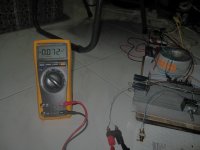
1. The rectifier passed the test. Without the cap, the output between V and PG for both rails is 36.2VDC. You said it should be approximately +-20Vdc without cap, and 30+ with cap.
Is it too high on my board? I used toroid 230v-25v x 2.
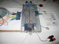
Then I finished soldering parts as in the first picture.
2. I connect the PS to two amp boards and used star ground. For testing, I soldered the star ground to the ground line of home electric net. An ALPS 50k is used for volume.
Now is the result of dry test with no load:
- In the first time turn on, volume is completely down, left channel offset was -25mV and right channel offset was about +32mV! I turned the volume up, left channel went up to -70mV and right channel went to -27mV. Is it abnormal?
- Turn the amp off and no speaker connect, I could see the offset jumped to 4.36V.
- I let the amp run with no input and no output for more than 3 hours, the left channel offset values is the same as the first test (-25mV with min volume and -70mV with max volume). However, the right channel, something strange (i think) happened: with the volume set completely down, the offset value was changing gradually from +32mV to -14mV and the offset when volume was set maximum was also adjusted accordingly and the last value I could measure was -53mV or so.
I don't understand this. Could you please advise?
By the way, one of the 1500uF cap has a little distortion on its cover when I first checked parts from the delivered package. I thought it is OK anyway and continue as you can see. However, the above phenomenon is accidently occuring to the board with that cap on.
Is it true that the distorted cap (just a little) does not work properly?
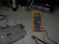
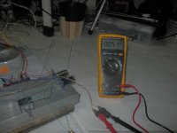
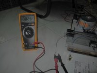
For your reference, the 2nd, 3rd, 4th and 5th pics were captured the offset values (volume set minimum and maximum respectively) of right and left channel during test.
3. I left the amp run with no input and output load for more than 3 hours. Is it equivalent to running the amp with in/out load in the same amount of time?
Many Thanks.
After a week could not touch the board, I can continue my project this weekend.
1. The rectifier passed the test. Without the cap, the output between V and PG for both rails is 36.2VDC. You said it should be approximately +-20Vdc without cap, and 30+ with cap.
Is it too high on my board? I used toroid 230v-25v x 2.
Then I finished soldering parts as in the first picture.
2. I connect the PS to two amp boards and used star ground. For testing, I soldered the star ground to the ground line of home electric net. An ALPS 50k is used for volume.
Now is the result of dry test with no load:
- In the first time turn on, volume is completely down, left channel offset was -25mV and right channel offset was about +32mV! I turned the volume up, left channel went up to -70mV and right channel went to -27mV. Is it abnormal?
- Turn the amp off and no speaker connect, I could see the offset jumped to 4.36V.
- I let the amp run with no input and no output for more than 3 hours, the left channel offset values is the same as the first test (-25mV with min volume and -70mV with max volume). However, the right channel, something strange (i think) happened: with the volume set completely down, the offset value was changing gradually from +32mV to -14mV and the offset when volume was set maximum was also adjusted accordingly and the last value I could measure was -53mV or so.
I don't understand this. Could you please advise?
By the way, one of the 1500uF cap has a little distortion on its cover when I first checked parts from the delivered package. I thought it is OK anyway and continue as you can see. However, the above phenomenon is accidently occuring to the board with that cap on.
Is it true that the distorted cap (just a little) does not work properly?
For your reference, the 2nd, 3rd, 4th and 5th pics were captured the offset values (volume set minimum and maximum respectively) of right and left channel during test.
3. I left the amp run with no input and output load for more than 3 hours. Is it equivalent to running the amp with in/out load in the same amount of time?
Many Thanks.
Attachments
My voltage suggestions were for 22V transformer, what you are getting with your 25V unit is perfectly fine. Please also note that voltage variation will depend on output from the wall and it may be off 10% off from nominal rating and on regulation margin of transformer (the voltages are listed at full load, which you won't see with that amp)
Now is the result of dry test with no load:
- In the first time turn on, volume is completely down, left channel offset was -25mV and right channel offset was about +32mV! I turned the volume up, left channel went up to -70mV and right channel went to -27mV. Is it abnormal?
- Turn the amp off and no speaker connect, I could see the offset jumped to 4.36V.
This is perfectly normal and that's what I was trying to point out in post here: http://www.diyaudio.com/forums/audi...kit-building-instructions-69.html#post2459586
The offset will depend on a particular chip and is subject to shunt resistance (22k) at amp's input. Adding pot in parallel with that resistance will affect combined shunt resistance value and that's why you see those changes when pot turning. When you add coupling cap between pot and the amp, the shunt resistance value is not affected by pot rotation, but since it's always 22k the offset will be also highest, that's why I said that adding coupling cap may actually increase your offset (-70mV vs -25mV for left channel, with a right channel there is no so much difference as offset balances nicely through 0 point).
This is also true for amp with no pot and low output impedance source connected. You will always see a drop in DC offset when connecting source, you won't see that effect with coupling cap in place. BTW, I measured offsets on 47Labs Gaincard and they were approx 80mV.
4.36V at shut down is normal with no load, when speakers are connected, it doesn't happen.
Last edited:
By the way, one of the 1500uF cap has a little distortion on its cover when I first checked parts from the delivered package. I thought it is OK anyway and continue as you can see. However, the above phenomenon is accidently occuring to the board with that cap on.
Is it true that the distorted cap (just a little) does not work properly?
3. I left the amp run with no input and output load for more than 3 hours. Is it equivalent to running the amp with in/out load in the same amount of time?
The cap has nothing to do with that, and slight blemish does not affect anything here.
I can't comment on point 3; it could be the same or it might be not, but it's best to burn in the amp with signal and the load.
My GC is working and new questions
Peter,
I finished all soldering work and test and could not wait to check the amp till this weekend. So yesterday night, I connected the amp to a Jamo rear surround (1 cone - 8ohm) borrowed from landlord") just for testing. It worked, the amp is working now, two channels.
just for testing. It worked, the amp is working now, two channels.
I could feel the clarity of high frequencies but could not test med and bass. I think just because the speaker has only 1 cone and cannot cover all freq. "Burning" it for about 2 hours while enjoying music from the system. That's an amazing feeling having my first diy audio working.
I can say that the sounds is so good, very clear and really really nice to my ears. I particularly love the vocal from Eva Cassidy - Fields of Gold, Diana Krall and Norah Jones. I could feel the clear crack in the voice of Tom Waits in Big in Japan. The flute in symphony by Aaron Copland also very clear and smooth.
More than that, the amp makes no hum, completely quiet and no "thump" when turning power switch on/off (I still use the switch on power cord in this test) and plug in/out the input cable from my computer to the amp. It definetely beats my current cheapo computer speaker Altec Lansing 2.1.
That's a great work, Peter ! I am very happy ! Thank you so much for very detailed instruction and also thanks other people for Q&As here. I learned a lot.
My new questions, Peter.
1. I measured the voltage between PG and V outputs of rectifier. Without the caps, the voltage is 36.15Vdc. As far as I know, with the caps on rectifier, the voltage will be more than 36Vdc, right? Will it be OK using those caps. What and how will the performance be affected with/without the supplied caps (10uF) on rectifier?
2. In post #50 (http://www.diyaudio.com/forums/audi...-kit-building-instructions-5.html#post1516500), you commented "Without R1 the sound will be more neutral and transparent, especially with Premium kit.
I supply that resistor "just in case", to provide some isolation for amp's input.
"
I am using the Premium kit with R1 onboard. Is that the reason that the amp makes no hump and thump when I turn main power on/off and plug input cable in/out the computer soundcard?
I will try the amp without R1 later, with proper speakers, in order to look for better listening.
3. I know that not just the amp but the speakers also make a greate enjoyment. Pity that I don't have a good speakers for testing.
Would you have suggestion to select a good bookshelf speaker?
What do I need to make the GC amp for a 2.1 speaker system?
My Altec Lansing 2.1 is 8ohm with built-in amp. Is there anyway to use GC amp for the speakers?
Many thanks.
HT
Peter,
I finished all soldering work and test and could not wait to check the amp till this weekend. So yesterday night, I connected the amp to a Jamo rear surround (1 cone - 8ohm) borrowed from landlord
just for testing. It worked, the amp is working now, two channels. I could feel the clarity of high frequencies but could not test med and bass. I think just because the speaker has only 1 cone and cannot cover all freq. "Burning" it for about 2 hours while enjoying music from the system. That's an amazing feeling having my first diy audio working.
I can say that the sounds is so good, very clear and really really nice to my ears. I particularly love the vocal from Eva Cassidy - Fields of Gold, Diana Krall and Norah Jones. I could feel the clear crack in the voice of Tom Waits in Big in Japan. The flute in symphony by Aaron Copland also very clear and smooth.
More than that, the amp makes no hum, completely quiet and no "thump" when turning power switch on/off (I still use the switch on power cord in this test) and plug in/out the input cable from my computer to the amp. It definetely beats my current cheapo computer speaker Altec Lansing 2.1.
That's a great work, Peter ! I am very happy
! Thank you so much for very detailed instruction and also thanks other people for Q&As here. I learned a lot. My new questions, Peter.
1. I measured the voltage between PG and V outputs of rectifier. Without the caps, the voltage is 36.15Vdc. As far as I know, with the caps on rectifier, the voltage will be more than 36Vdc, right? Will it be OK using those caps. What and how will the performance be affected with/without the supplied caps (10uF) on rectifier?
2. In post #50 (http://www.diyaudio.com/forums/audi...-kit-building-instructions-5.html#post1516500), you commented "Without R1 the sound will be more neutral and transparent, especially with Premium kit.
I supply that resistor "just in case", to provide some isolation for amp's input.
"
I am using the Premium kit with R1 onboard. Is that the reason that the amp makes no hump and thump when I turn main power on/off and plug input cable in/out the computer soundcard?
I will try the amp without R1 later, with proper speakers, in order to look for better listening.
3. I know that not just the amp but the speakers also make a greate enjoyment. Pity that I don't have a good speakers for testing.
Would you have suggestion to select a good bookshelf speaker?
What do I need to make the GC amp for a 2.1 speaker system?
My Altec Lansing 2.1 is 8ohm with built-in amp. Is there anyway to use GC amp for the speakers?
Many thanks.
HT
The voltage won't change as you already have caps on amp board; adding more caps on rectifier board won't affect the voltage.
The R1 has no influence on thump, removing it should make the amp more transparent, but you also need transparent system to observe it,
I'm not familiar with commercial speaker offerings, choose something reasonably efficient with simple crossover, maybe Epos ES11: http://www.diyaudio.com/forums/chip...s-loudspeaker-listen-our-gc-3.html#post784828
For 2.1 you will need another half a kit.
You could disconnect the amps from drivers in your AL system and connect GC.
Transformer
Hello Peter, still enjoying the amp I built last year. I just purchased a couple transformers from Antek, one for a 15v preamp supply and one for a future GC. The Anteks now have a static shield between primary and secondary coils to improve the isolation and noise interference. I'm not sure how to implement this extra wire. Here's a link to the Antek. Antek - AS-3225
Any suggestions? Thanks
SO i've been using my kit for over a year i think, its not in a case but bolted to a chunk of aluminum and has worked wonders since I built it. The other day I decided to finally build a pre-amp/switch box. I moved the volume pot from the amp to the pre inbetween the two 3-way switches (3 ins, 3 outs, 1 of the outs buffered). and no matter what, I am picking up radio signals. The only way I can get rid of it is to add a pot back to the amp where I had it before and with anything above 0 and below 100 its fine.
I've tried shielded hook up wire, re routing it, everything. It's been 3 nights of trying to solve this and now I am tired!
Any ideas?
(I just tried with a headphone amp and it doesnt seem to do it)
I've tried shielded hook up wire, re routing it, everything. It's been 3 nights of trying to solve this and now I am tired!
Any ideas?
(I just tried with a headphone amp and it doesnt seem to do it)
SO i've been using my kit for over a year i think, its not in a case but bolted to a chunk of aluminum and has worked wonders since I built it. The other day I decided to finally build a pre-amp/switch box. I moved the volume pot from the amp to the pre inbetween the two 3-way switches (3 ins, 3 outs, 1 of the outs buffered). and no matter what, I am picking up radio signals. The only way I can get rid of it is to add a pot back to the amp where I had it before and with anything above 0 and below 100 its fine.
I've tried shielded hook up wire, re routing it, everything. It's been 3 nights of trying to solve this and now I am tired!
Any ideas?
(I just tried with a headphone amp and it doesnt seem to do it)
You need to try this: http://www.diyaudio.com/forums/audi...-kit-building-instructions-3.html#post1516522
It would be wired the same way as two LM3886 in this schematic: http://www.audiosector.com/lm4780 amp.pdf
- Home
- More Vendors...
- Audio Sector
- Commercial Gainclone kit- building instructions