Hi, I have armed the VSPS400 using some components of my previous VSPS300.
I do not know why I had a Humm problem even though the assembly was the same as the one I did for VSPS300. The only way to improve it was by placing shielded cables and at the input a 2k2 resistor after the 47k load resistor.
With volume at the maximum a slight Humm is perceived.
Could it be that I have used OPA27 instead of OPA134 ?.
Better performance can be obtained with OPA134 ?.
I am waiting for him.
Anyway, in my first listenings gives the impression that there is a slight increase in low frequencies and half frequencies.
The sound scene seems to acquire more space forward and backward.
I will wait for the OPA134 and I will see if there are differences.
I worry about the Humm, although I have already solved it to a large extent.
What harm can the 2k2 resistor cause at the input of the operational amplifier? (I'm left with the desire to assemble the Emerald).
Greetings, Josè
An externally hosted image should be here but it was not working when we last tested it.
An externally hosted image should be here but it was not working when we last tested it.
Hi Jose,
Normally there's no hum, just a "shshshsh" sound with the volume turned up. Since shielding the inputs reduced the hum, it seems like it is just common interference between the power supply and the input signal - though this is unusual and nothing in your build suggests any problems. Does it still hum, or hum more, with the input disconnected?
To answer - no, changing to OP134 shouldn't affect anything, though you never know...
Adding a 2.2k resistor in series with the op amp input in effect creates a low pass filter with the input capacitance, so it is something of an RFI killer. It does increase the overall circuit noise a little though.
Richard
With input connected only SHSHSH appears.
But with the volume at a listening level of music, the HUMM is not noticed.
Could it be that this HUMM not audible at the listening level interferes with and distorts the music, even if it is not perceived?
I do not have another turntable to try.
But with the volume at a listening level of music, the HUMM is not noticed.
Could it be that this HUMM not audible at the listening level interferes with and distorts the music, even if it is not perceived?
I do not have another turntable to try.
And you have reached 400 pages in your thread
I couldn't have done it without you.

1. There is always some input capacitance from the board layout, input transistors etc.
2. The default VSPS value of R2 681 ohms will give 40 dB which should be fine. If you want to lower the gain a bit, use 1k or 1.2k.
3. The VSPS is normally noisier with no input connected (open input) than with the cartridge attached. That you hear no hum in open input condition means the problem is not the VSPS per se. but something to do with the cartridge and its connection and cabling.
I made this cable and the HUMM went.
You were right, the problem is the turntable cable.
I do not know why it used to work and not now. But problem solved.
Cables Apantallados en Audio y R.F. - El portal del sonido analogico
You were right, the problem is the turntable cable.
I do not know why it used to work and not now. But problem solved.
An externally hosted image should be here but it was not working when we last tested it.
Cables Apantallados en Audio y R.F. - El portal del sonido analogico
Last edited:
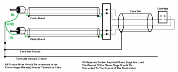
That wiring diagram is fairly conventional, the difference from normal is the connection from the cable shield is taken externally to the ground. Typically it connects to the RCA shield connects to IN- and routes to GND through the board.
I suppose the setup is a bit cumbersome around the RCA jacks, but it it technically rigorous and should give the best shielding.
I suppose the setup is a bit cumbersome around the RCA jacks, but it it technically rigorous and should give the best shielding.
It's more like "double shielding" the input wires. There's an additional measure of protection against electrostatic noise, since the outer shield is wired separately from the IN- signal return. The signal return is just part of the inner twisted pair.
Normally the shield is connected back to the signal return at the RCA jack, as shown.
Normally the shield is connected back to the signal return at the RCA jack, as shown.
Attachments
VSPS 5.2b2 BOM
Changed the stereo VSPS BOM.
The LM7812CT and LM7912CT are end-of-life, the new part is the LM7812CT/NOPB and LM7912CT/NOPB. Mouser sells the new-lead free version by TI, vs. the old one which was a Fairchild/On semi part. The Fairchild regulators are cheaper and still available, though backordered as of this writing.
/R
Attachments
Last edited:
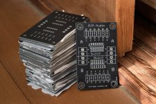
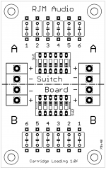
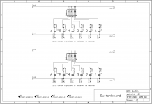
The SwitchBoard has been updated to rev. 1.0f. and project status moved to "production".
There is almost no change, none significant, from the earlier 1.0d boards.
There is almost no change, none significant, from the earlier 1.0d boards.
Attachments
Hello Richard. I'm building the Esmeralda, using Dale 1% resistors and Wima capacitors. I have adjusted the values exactly to the circuit, measuring each component and matching both channels. The bad thing is that I am using a DIY PCB made with a marker and iron perchloride.
I will see how it turns out.
Out of curiosity, could you give me the sensitivity values of the circuit or the mV limit of its overload, or how many mV does the input begin to cut?
I have read on the subject and I would be interested in these values.
Regards, Jose.
I will see how it turns out.
Out of curiosity, could you give me the sensitivity values of the circuit or the mV limit of its overload, or how many mV does the input begin to cut?
I have read on the subject and I would be interested in these values.
Regards, Jose.
Hi Jose,
So Emerald is Esmeralda in Spanish? Neat, I didn't know that!
So the Emerald (Esmeralda) [That is such a cool name, I should have called it that instead!] is designed with an LP filter in the interstage and a relatively low gain input stage. The overhead, or headroom, therefore, is determined entirely by the output stage and is independent of frequency - you can safely use the midband values for the calculation.
The exact values will depend on what gain you choose to set it up for, but the output is anyway fixed by the power supply rails, so it's about 6 V rms max or +15 dB for 1 V rms reference, but +25 dB against the nominal line level signal of -10 dB.
So to do the calculation for say the DL-103, which is 0.3 mV at 5 cm/s 1 khz, or -70 dB, you dial in 60 dB gain into the Emerald to bring that to -10 dB line level, with 25 dB of headroom to spare. If you used 57 dB gain, the headroom would increase to 28 dB, but the output signal is lower and you'll need to increase the volume level more to compensate. The point is you are always trying to bring the cartridge output (as referenced to 5 cm/s 1 kHz) to -10 dB for line level. Some recordings might exceed this slightly, but with 25 dB spare the Emerald should be able to take it in stride when the gain is configured in this fashion.
Last edited:
I believe that yes, that the translation of Emerald in Spanish is emerald but I am not very sure.
Anyway, I call your preamp Esmeralda.
Thank you very much for explaining the topic of headroom or overhead.
When the project ends, I tell you.
Greetings. (I'm almost giving up medicine for assembling phono preamps. Ja Ja)
Anyway, I call your preamp Esmeralda.
Thank you very much for explaining the topic of headroom or overhead.
When the project ends, I tell you.
Greetings. (I'm almost giving up medicine for assembling phono preamps. Ja Ja)
My Emerald
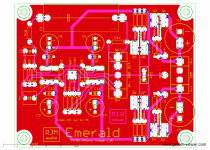
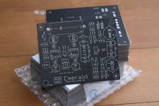
I received my Emerald 1.0t and the latest switch board a few weeks ago. Richard, the boards look wonderful as usual, you can tell the care and attention that went to get the layout to revision "t".
After an initial order of parts from DigiKey, I have the Emerald partially completed, with most of the case work already done. Only a few more components on the way to complete the switch board, along with replacements for some mis-ordered resistors. I wanted to share the details of my build and my progress so far.
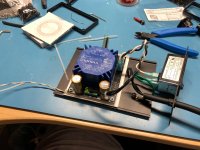
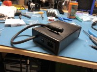
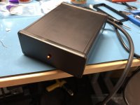
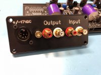
The power supply is constructed using a PCB mounted transformer circuit I had originally designed for the Sapphire. It fits Talema's 25va transformers (or their competitors' duplicate) as well as discrete rectifier diodes, smoothing caps, and some other extras. I am running the umbilical cord to the Emerald chassis using a cable that has two independently shielded 24awg twisted pairs. These run to each channel via a 6 pin Neutrik XLR connect. I have this fit into a Hammond 1455Q1601BK enclosure, along with a filtered and fused IEC module.
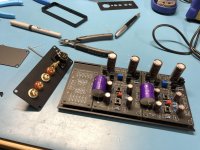
The Emerald boards and switch board are housed in an identical, but longer, Hammond 1455Q2201BK. I am trying out Clarity Caps' new CSA line for the coupling cap. I needed some other parts from PartsConnexion, so I am going to try out Amtrans fancy AMRG carbon film resistors for C10, if for no other reason than the looks (see Amtrans AMRG Carbon Film Resistors | Hifi Collective).
I can't wait for the last shipment of components to arrive so I can try the Emerald out. It's been an incredibly fun build so far and I really appreciate the work that Richard puts into his projects.
I received my Emerald 1.0t and the latest switch board a few weeks ago. Richard, the boards look wonderful as usual, you can tell the care and attention that went to get the layout to revision "t"
.After an initial order of parts from DigiKey, I have the Emerald partially completed, with most of the case work already done. Only a few more components on the way to complete the switch board, along with replacements for some mis-ordered resistors. I wanted to share the details of my build and my progress so far.
The power supply is constructed using a PCB mounted transformer circuit I had originally designed for the Sapphire. It fits Talema's 25va transformers (or their competitors' duplicate) as well as discrete rectifier diodes, smoothing caps, and some other extras. I am running the umbilical cord to the Emerald chassis using a cable that has two independently shielded 24awg twisted pairs. These run to each channel via a 6 pin Neutrik XLR connect. I have this fit into a Hammond 1455Q1601BK enclosure, along with a filtered and fused IEC module.
The Emerald boards and switch board are housed in an identical, but longer, Hammond 1455Q2201BK. I am trying out Clarity Caps' new CSA line for the coupling cap. I needed some other parts from PartsConnexion, so I am going to try out Amtrans fancy AMRG carbon film resistors for C10, if for no other reason than the looks (see Amtrans AMRG Carbon Film Resistors | Hifi Collective).
I can't wait for the last shipment of components to arrive so I can try the Emerald out. It's been an incredibly fun build so far and I really appreciate the work that Richard puts into his projects.
Attachments
- Home
- Source & Line
- Analogue Source
- The Phonoclone and VSPS PCB Help Desk