Nordic said:Just want to report, that I removed the output caps from my VSPS, and I am now 100% happy, in fact when my wife wanted to watch TV, she tried to turn off the CD player to stop the music, thats how good it sounds.
What is the output dc,with and with output cap?
E&E,
It might be that the problem is the gain set resistors not the RIAA components anyway. I'd measure R2 and R3 to check they closely match between channels, too.
Now, the tough question: how many dB equals how much position shift. Based on my experiences this week, 0.5 dB in the treble is enough to completely move a cymbal across to the other side of the stage. The bass frequencies are less critical.
So, my wild guess based on your description is that you are looking at a gain error in the range of 0.25 dB. Which translates to, roughly, a 3% difference in the resistance or capacitance.
If you cant find the component that seems suspect, then just increase or decrease one of the gain components (R2,R3) at random by that amount. A band-aid fix, but it will help at least.
Increase R2, more gain. Increase R3, less gain.
The moral of this story seems to be: match everything as tightly as you possibly can. 1% is a reasonable goal for the resistors R2,R3, R5, and R6, 2% for the caps C1 and C2. Unfortunatly its the caps which are usually the problem. R1, R4, R7 and R8 are non-critical.
PS everything shipped last Friday.
Szabcsi,
See the Phonoclone homepage. Values listed give RIAA accuracy to 0.1 dB. I can give you the exact-to-n-decimal values if you care to contact me.
/R
Hi Richard, why not posting the values right here?rjm said:
I can give you the exact-to-n-decimal values if you care to contact me.
/R
Rüdiger
Nordic said:Can't remeber now, but it was negligible... 1 digit stuff..
I dont want to assume anything,do you remember which digit?
riaa network values
Hi Richard,
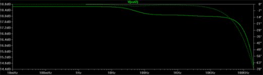
I have both build and 'sim-ed' the phonoclone. My sim shows a -0.5db 'step' down at 200Hz.
With 699k instead of 750k it's nearly flat. The other values seem spot-on. How did you measure the response, on the real thing, simulation software, or 'just' calculated?
I will try with around 700k on the real circuit, unfortunatley, I cannot measure the real thing (yet).
Rüdiger
edit: as soon I#ve found out how to grafik-convert the sim-plots i will post them...
Hi Richard,
I have both build and 'sim-ed' the phonoclone. My sim shows a -0.5db 'step' down at 200Hz.
With 699k instead of 750k it's nearly flat. The other values seem spot-on. How did you measure the response, on the real thing, simulation software, or 'just' calculated?
I will try with around 700k on the real circuit, unfortunatley, I cannot measure the real thing (yet).
Rüdiger
edit: as soon I#ve found out how to grafik-convert the sim-plots i will post them...
My sim shows a -0.5db 'step' down at 200Hz. With 699k instead of 750k it's nearly flat.
R6 (750k) does indeed control the bass response. However, decreasing the value will decrease the gain at low frequencies, not increase it. [Approximately, the gain in this region is ~ R6/R3]
Your simulation does not appear to be behaving correctly.
When I substitute 699k for 750k in my worksheet, I go from having a flat bass response (ignoring the output coupling cap for now) to having a -0.5dB step at 20 Hz not 200 Hz.
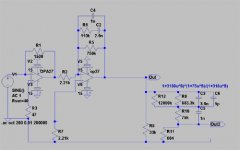
My values are R5 = 110k R6 = 750k C1 = 1.0 nF and C2 = 2.9 nF. My "simulation" is just a calculation of the gain, Z1/R3, where Z1 is the complex impedance of the network R5, R6, C1 and C2:
Z1 = 1/[1/R6 + 1/(R5+Xc(C2)) + 1/Xc(C1)]
where Xc(c) = 1/(i w c), and w = 2 p f .
I use MathCAD since with this software its easy to manipulate the complex numbers directly. The calculated gain is compared to the ideal RIAA response curve defined by the three reference time constants.
Its not the most elegant approach, but its simple and gets the job done with the minimum of fuss. The op-amp bandwidth and bass rolloff due to C3||outputZ can be added at the end if desired.
I measured various Phonoclone versions and found that they all conformed to the simulation within the error introduced by the capacitance tolerances. No dip at 200Hz was ever observed.
/Richard
PS Hopefully with this info you'll be able to confirm this yourself. A good self-check is to use Walt Jung's values for a passive filter, here for example, and see if you can replicate a flat RIAA reponse.
See also
Chapter 6 of this Analog Devices document, or the datasheet for this TI op-amp.
Walt Jungs values and mine are the same ratio, just slightly different approximations.
For his N2 network, the exact values are
7.290k 1.06k 0.1029u 0.300u
which he approximates to
7.32k, 1.05k, 100n (103n on the original app note, simplified to just 100n in the OPA606 circuit), 300n
and I approximated as (by hand, not previously knowing the exact values)
7.22k 1.05k 104n 303n
or, in the phonoclone circuit as
750k, 110k, 1n, 2.9n
These are both slightly closer than OPA606 circuit, which was already good to +/- 0.1 dB.
Just remember that to recalculate the ratio, you multiply the caps by x and divide the resistances by x.
/R
The discrepancy comes from the method for generating the reference RIAA response used to compare the phonoclone's output to. I used the exact time constants to generate the RIAA curve. You've used a second passive filter at the output of your circuit to perform reverse eq. The problem is the passive filter, which is only approximately correct.
/Richard
/Richard
Power Supply Help
I have built the VSPS and I am powering it with a regulated +-12 VDC supply (Welborne). I am very happy with the results. However, I want to put the VSPS in a preamp I have built and would like to power it with the existing power supply. The preamp has dual unregulated +-32 VDC available. It seems that a drop from 32 VDC to 15 VDC would generate a lot of heat if it is even possible. Is there any way to use this supply to power the VSPS? This supply also powers the line stage, which has on board regulation to 24 VDC.
Thanks for a fantastic project and thread.
The heat dissipation will only be in the order of 1/4W per regulator. The voltage drop is also well within the datasheet limits for the LM7815 etc.
The circuit current is small, that's why its not such a problem.
You could add a small heatsink to the regulators, but it is not really needed. The temperature will only increase about 10 deg C above ambient.
Do, however, make sure the filter capacitors at the egulator input are rated for 35V or more, not 25V.
/R
Re: Power Supply Help
you could just use 2 pairs of resistor network to get the required unregulated 15v. one pair for + and another for -, then connect as per normal to your existin vsps.
LHMAudio said:However, I want to put the VSPS in a preamp I have built and would like to power it with the existing power supply. The preamp has dual unregulated +-32 VDC available. It seems that a drop from 32 VDC to 15 VDC would generate a lot of heat if it is even possible. Is there any way to use this supply to power the VSPS? This supply also powers the line stage, which has on board regulation to 24 VDC.
you could just use 2 pairs of resistor network to get the required unregulated 15v. one pair for + and another for -, then connect as per normal to your existin vsps.
Hi,
This is true, see http://www.diyaudio.com/forums/showthread.php?postid=860056#post860056
where the plot shows the same step using that inverse network.
With a laplace transform function in ltspice the deviation is about 0.1dB max.
Rüdiger
rjm said:The discrepancy comes from the method for generating the reference RIAA response used to compare the phonoclone's output to. I used the exact time constants to generate the RIAA curve. You've used a second passive filter at the output of your circuit to perform reverse eq. The problem is the passive filter, which is only approximately correct.
/Richard
This is true, see http://www.diyaudio.com/forums/showthread.php?postid=860056#post860056
where the plot shows the same step using that inverse network.
With a laplace transform function in ltspice the deviation is about 0.1dB max.
Rüdiger
Transformer Selection
I have had a couple of people recently asking about which transformer they should get. The recommendation hasn't changed: 50 VA, toroid, 2x 12V secondaries. What I want to detail here are your options within that.
First off, if you go to Digikey and type toroid, you find theres a bug with the search engine.
If you select Transformers - PC mount, you can pick from the 70000 series, the transformers encapsulated in the blue heasink that mount directly on a circuit board. Not so useful.
If you select Transformers - Toroidal, you can pick from Amveco or Hammond standard power transformers. Setting 12V and 50 VA, you are given the choice between 182L12 from Hammond at $43 or the Amveco AA50502-012 at $84.
What you don't find are the ones you really want, the Amveco low profile miniature toroids, 60000 series. The part number for the 50 VA, 12V model is 62082 and it costs less than $19.
The problem is the description, "TRANSFRMR 12V 4.166A WITH WIRES", doesn't include the word toroid, so the series is excluded from the search results. If you use the print catalog or the .pdf version this isn't an issue as its all right in front of you.
The Amveco 62082 is at the moment the best option considering the price. The only downside is you dont get the option of an electrostatic screen or a magnetic shield. For that you'll need to talk to Plitron and it will cost you about 3-4 times more.
If you are not getting the 62082 and instead picking from standard power transformer models then you might want to think about going with larger capacity model, 160-225 VA. The price increase compared to 50 VA is less than 20%, and the bigger transformer will sound better and be more versatile for use later with other projects.
That's a North America-centric view of the supply situation, as seen through my Internet glasses.
Richard
The part number for the 50 VA, 12V model is 62082 and it costs less than $19
If that's out of stock, go with the smaller 35 VA model, 62072, at $17.
Two of those in dual mono gives you 70 VA total for $10 less than the cost of a single 50 VA or 80 VA Hammond equivalent.
/R
- Home
- Source & Line
- Analogue Source
- The Phonoclone and VSPS PCB Help Desk