As I am willing to capture all my LP collection to digital, one of the first steps is to arrange a very good RIAA preamp.
One problem, for me at least, seems how to simulate low level signal preamps, as the ones I have been trying do not behave as I think they should.
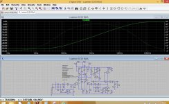
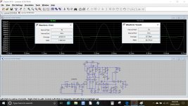
Take, for instance, the Luyxman 5C50 RIAA preamp I uploaded. As it is shown, with an anti-RIAA passive network at the input (which apparently is how to simulate a RIAA preamp), I am getting a very low output signal, as if there was no amplification at all.
So, first of all, am I implementing the anti-RIAA filter as it should?
Now, if I bypass the filter, the signal level at the output is still low. Not in several volts as I think it should, but in less than 100mV at 1KHz.
Can someone tell me if I am doing something wrong or if there's something wrong in the preamp itself?
Just to check the preamp, I bypassed the RIAA network and increased R107 ten times, and this time I got the amplification I expected. So the amp is preamping. Adding then the RIAA eq still gets the preamping. But it all crumbles down as the input filter is included.
So for now my suspicions are on that filter. Is something wrong with it?
One problem, for me at least, seems how to simulate low level signal preamps, as the ones I have been trying do not behave as I think they should.
Take, for instance, the Luyxman 5C50 RIAA preamp I uploaded. As it is shown, with an anti-RIAA passive network at the input (which apparently is how to simulate a RIAA preamp), I am getting a very low output signal, as if there was no amplification at all.
So, first of all, am I implementing the anti-RIAA filter as it should?
Now, if I bypass the filter, the signal level at the output is still low. Not in several volts as I think it should, but in less than 100mV at 1KHz.
Can someone tell me if I am doing something wrong or if there's something wrong in the preamp itself?
Just to check the preamp, I bypassed the RIAA network and increased R107 ten times, and this time I got the amplification I expected. So the amp is preamping. Adding then the RIAA eq still gets the preamping. But it all crumbles down as the input filter is included.
So for now my suspicions are on that filter. Is something wrong with it?
Attachments
am I implementing the anti-RIAA filter as it should? Can someone tell me
if I am doing something wrong or if there's something wrong in the preamp itself?
Can you post the schematics for both?
Both what? The schematics is on the simulation.
https://www.vintageshifi.com/repertoire-pdf/pdf/telecharge.php?pdf=Luxman-5-C-50-Service-Manual.pdf
https://www.vintageshifi.com/repertoire-pdf/pdf/telecharge.php?pdf=Luxman-5-C-50-Service-Manual.pdf
A passive RIAA preemphasis will attenuate mid-band (around 1 kHz) by 20 dB. Your amplifier should gave a gain of 34 to 40 dB at 1 kHz. This makes 14 to 20 dB with anti-RIAA. Now if your input signal is 5 mV, you will get 25 to 50 mV output. But driven by a real cartridge, you will get 10x signal, that is 250 to 500 mV as it should be.
Also note that not everybody has LTSpice installed, so I don't know what did you simulate
Also note that not everybody has LTSpice installed, so I don't know what did you simulate
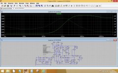
This shows the output of your inverse RIAA and then the output of the preamp. I would have to research what levels would be expected from the RIAA network but your version does produce a definite curve. Your preamp output is very non linear, I would check the time constants.
Attachments
This might turn out to be a question of theoretical versus practical results.
Let's start from the practical side, which is the one I know. That preamp is one of the best sounding there is. At the time of its release it had superlative reviews, with excellent measurements.
Recently we captured an LP using that preamp, where you can hear into the recording and see some flaws in it. Not many RIAA preamps can do that.
So if any problems turn out in the simulation, my bet is the problem is in the simulation, not in the preamp. The idea is to make the simulating tool better, not the preamp.
My intention is to get to accurate and realistic ways to make the simulations give some hint on why the preamp sounds as it sounds, and to compare others to it.
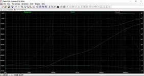
Like this ") and your overall frequency response is the flat line at -18db
and your overall frequency response is the flat line at -18db
The generator has a reference level of 0db. It is 0db because we set the voltage source to have a '1' in the 'AC Amplitude' box. That is the standard value to use. This setting is used for the AC analysis run of the simulation and overrides whatever amplitude you have set in the normal way.
If you made that number 3 (for example) then the voltage source would have a starting value of 9.5db. It works like this. The level is 20log (V1/V2), so that is 20log(3/1) which is 9.5.
If we made it 27 then the starting amplitude would be 28.6db. 20log(27/1)
Try it
It is our reference voltage. I've also given it a 300 ohm series output impedance although that will make little difference.
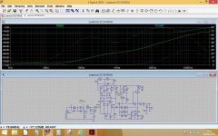
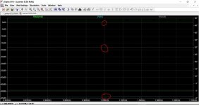
So we have 0db applied to the input of the inverse RIAA. The output of the RIAA is a curve following the official time constants. That gives our voltage 'Vin' which we apply to the amplifier.
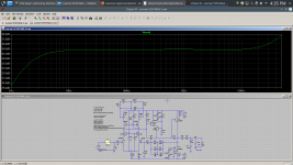
Pick a point on the curve (say 1kHz) and look at the amplitudes. The input to the amp is -54db down at 1kHz as applied to the amp via the inverse RIAA network.
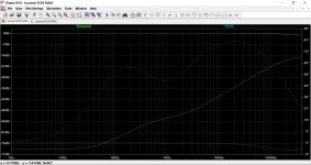
Now add the output of the amplifier to the traces and we can see that at 1kHz the output is at -18db.The third image is a close up of that. So the gain of the amplifier at 1kHz is -54 - -18 which is 36 or 36db.
Lets prove it works by changing the simulation to a normal analysis and apply a sine wave of 1kHz.
Now we can see that we have 1.4mv applied to the amp input, and we get 88.2mv output.
Gain equals 20log (Vout/Vin) which is (see last image). It agrees 100%.
and your overall frequency response is the flat line at -18dbThe generator has a reference level of 0db. It is 0db because we set the voltage source to have a '1' in the 'AC Amplitude' box. That is the standard value to use. This setting is used for the AC analysis run of the simulation and overrides whatever amplitude you have set in the normal way.
If you made that number 3 (for example) then the voltage source would have a starting value of 9.5db. It works like this. The level is 20log (V1/V2), so that is 20log(3/1) which is 9.5.
If we made it 27 then the starting amplitude would be 28.6db. 20log(27/1)
Try it
It is our reference voltage. I've also given it a 300 ohm series output impedance although that will make little difference.
So we have 0db applied to the input of the inverse RIAA. The output of the RIAA is a curve following the official time constants. That gives our voltage 'Vin' which we apply to the amplifier.
Pick a point on the curve (say 1kHz) and look at the amplitudes. The input to the amp is -54db down at 1kHz as applied to the amp via the inverse RIAA network.
Now add the output of the amplifier to the traces and we can see that at 1kHz the output is at -18db.The third image is a close up of that. So the gain of the amplifier at 1kHz is -54 - -18 which is 36 or 36db.
Lets prove it works by changing the simulation to a normal analysis and apply a sine wave of 1kHz.
Now we can see that we have 1.4mv applied to the amp input, and we get 88.2mv output.
Gain equals 20log (Vout/Vin) which is
(see last image). It agrees 100%.Attachments
When you do a sim such as this, don't forget to add a load on the output. I've added 50k (270k || 50k =42k) and 250pf for cable and input capacitance. I've used typical values, as I have really no idea exactly what kind of load this preamp will see.
I used a Laplace for the inverse RIAA.
I used a Laplace for the inverse RIAA.
Attachments
Another thing I would like to discuss, or at least listen to opinions on, is how to better implement your RIAA eq.
There was a two-part RIAA preamp FET construction project, signed by the engineer Erno Borbely, published in 1985 in The Audio Amateur.
I assembled a short pdf file where Borbely lists four ways that had been mostly used for RIAA filters, and he picks a fifth way which he finds best. These are:
1) Passive high=frequency roll-off on first stage
2) Active bass-boost on second stage
What I would like to do is simulate what Borbely did using other discrete blocks or ICs.
But I wonder if it's possible to anticipate any results, besides THD and frequency response. using LTSpice.
Attachments
...with an anti-RIAA passive network at the input ..., I am getting a very low output signal, as if there was no amplification at all. ....
Maybe this has been said better.
The preamp is active so it can have the GAIN we need.
The inverse-RIAA is usually implemented as a passive LOSS network. This avoids all doubts about active circuitry, is simpler, and is "OK" because our benchtop signal generator has a high-level output, while the preamp needs a low-level input.
It would be perfectly reasonable to design the inverse-RIAA for 100:1 loss @ 1KHz, design the preamp for 1:100 gain @ 1KHz, and have output SAME as input (+/- any errors). 1V in makes 1V out. Or if the inverse-RIAA were cut for 100:1 loss @ 1KHz and the preamp for 1:50 gain, then 1V in makes 0.5V out.
We want to cancel-out all those slopes to avoid tedious math. We want all signal levels "reasonable"; certainly on the bench though SPICE may not mind "1000V" calculated signals (in .AC mode). On the bench, both signal-generator and good preamp "reasonable" levels may be 0.1V to 5V or so. If the amp is as linear as good audio gear must be, it makes very little difference. Below that level hiss will contaminate readings, and of course any amplifier has overload which you want to stay away from.
What about this Laplace option to input an anti-RIAA signal in the preamp.
A friend of mine suggested this setup I'm uploading, which apparently is Laplace's, to watch at THD and AC response.
Can anyone explain a bit more to me on this procedure?
As I already tried this setup with another, but quite similar, RIAA preamp, and the THD results were practically the same at 1KHz (0.006%), I played a little more with the simulation and it puzzled me that THD @ 20KHz was less than that: 0.0009%. Is that possible?
Distortions usually increase at higher frequencies, at least with power amplifiers, so these results are surprising for me at least.
FR up to 20KHz is flat, so there's no signal attenuation to justify that THD decrease, apparently.
Is this behavior normal? Is the simulation OK?
Attachments
Hi!
I found the same in my simulations with a RIAA-stage.
I think it's because the THD is also increasing with the amplification ratio. But in a RIAA amplifier this is higher at low frequencies. Try the analysis in the range 20-200Hz, the THD will probably be shown orders of magnitude higher.
I found the same in my simulations with a RIAA-stage.
I think it's because the THD is also increasing with the amplification ratio. But in a RIAA amplifier this is higher at low frequencies. Try the analysis in the range 20-200Hz, the THD will probably be shown orders of magnitude higher.
- Status
- This old topic is closed. If you want to reopen this topic, contact a moderator using the "Report Post" button.
- Home
- Source & Line
- Analogue Source
- Low level signal simulations