This is very true. Hasn't stopped people who should know better selling devices to do this though.
The Cartridge Man Isolator for example
Edit: And I am ignoring your comment about pivoted damping at the bearings as I really cannot afford this") . SME FDIV Damper kit
. SME FDIV Damper kit
The Cartridge Man Isolator for example
Edit: And I am ignoring your comment about pivoted damping at the bearings as I really cannot afford this
. SME FDIV Damper kit
Last edited:
In designing and building my own unipivot arm, I put most of the damping in the vertical direction for warp damping, and less damping in the horizontal direction, instead relying on the zero offset angle of my linear tracker to reduce FM from horizontal scrubbing.
Ray K
Hans,Hi Ray,
Thanks for your contribution.
One question: How exactly did you put damping in the vert direction to your own arm ?
Hans
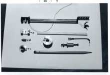
Damping is at the pivot, not especially different from the way damping has been implemented on other unipivots. In my case it was done by selecting the dimensions of the cylindrical bearing cup (part B in the photo) that’s submerged in a silicone oil bath in the pivot base (part C in the photo). For vertical motion the cylinder sloshes the silicone bath and sees significant damping effect. For horizontal motion the cylinder rotates axially in the silicone bath and the damping effect is less. The design was done empirically, so I am unable to offer any design calculations. Basically seat-of-the-pants engineering that worked out eminently well.
Ray K
http://www.diyaudio.com/forums/attachment.php?attachmentid=654455&stc=1&d=1515010686
Attachments
Re M97xE brush effect
Shure M97xE (on Pro-ject Debut Carbon arm) resonance test.
Brush up vs brush down
Shure TTR117 test record.
Source:
YouTube
Apply your analysis tools
brush up
Dropbox - Brush up.wav
brush down
Dropbox - Brush down.wav
George
Shure M97xE (on Pro-ject Debut Carbon arm) resonance test.
Brush up vs brush down
Shure TTR117 test record.
Source:
YouTube
Apply your analysis tools
brush up
Dropbox - Brush up.wav
brush down
Dropbox - Brush down.wav
George
Attachments
Shure M97xE (on Pro-ject Debut Carbon arm) resonance test.
Apply your analysis tools
George the analysis tool seems to have trouble labeling the low decade(s)? Getting flawless plotting of log axes especially with partial decades at either or both ends is a special exercise.
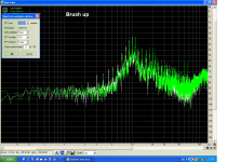
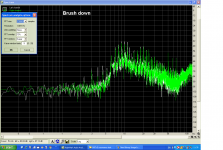
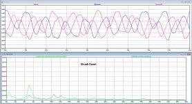
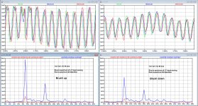
Here is the first output, 5 Hz modulating 2989 Hz and 2380 Hz.
With Brush Up, waving is considerable, almost exclusively vertical resonance (not separately shown here).
Taking the brush down, suppresses the resonance and waving because of that to a great degree.
IM distortion becomes 2.5 dB less, not as much as expected when looking at the waving.
More to follow.
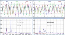
In the spectra below, light green is the IM spectrum and cyan the spectrum of the input signal waving caused by hor and vert resonance.
Hans
With Brush Up, waving is considerable, almost exclusively vertical resonance (not separately shown here).
Taking the brush down, suppresses the resonance and waving because of that to a great degree.
IM distortion becomes 2.5 dB less, not as much as expected when looking at the waving.
More to follow.
In the spectra below, light green is the IM spectrum and cyan the spectrum of the input signal waving caused by hor and vert resonance.
Hans
Attachments
Last edited:
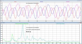
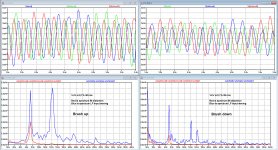
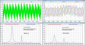
Now for 6 Hz plus both carriers at 2.4 and 3 KHz, brush up and brush down again showing IM for 3 LP revolutions.
Waving of LP input signal is again considerably lower with brush down, but with brush down IM at 5Hz is only 2.8 dB less, and still above the critical threshold of 0.1%.
Hans
Waving of LP input signal is again considerably lower with brush down, but with brush down IM at 5Hz is only 2.8 dB less, and still above the critical threshold of 0.1%.
Hans
Attachments
IM is caused by FM modulation.Hans,
Is this IM or FM?
What does the spectrum at 2.4KHz and 3 KHz look like?
Seeing IM components is not the same as seeing FM. The auditory phenomenon is different.
Ray K
I have displayed the FM modulation versus time for 3 LP revolutions.
The amplitude scale on the Y axis displays the percentage IM.
1mV equals 0.1 %.
The spectral lines are % IM in rms value.
Tones at 2.4 and 3Khz are having equal amplitude
Hans
I'm just displaying what happens, conclusion have to wait until all 10 recordings have been published, so far only 4 of them.It puzzles me to see that brush changed resonance frequency. In my experience, my silicone damper reduced the amplitude of resonance frequency only.
Hans
Assuming that IM/FM on both carriers is the same, I have looked at the 3 Khz carrier.Hans -
The IM/FM is on what carrier 2.4k, 3k, or even 600Hz?
Hans
Here's my submission, in summary form, attached.
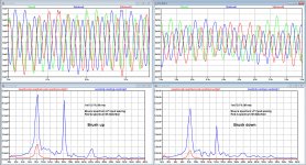
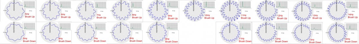
Looking at FM variation of the 3kHz carrier in the time domain, using polar plot format. For these plots, tramlines are at 0.2% spacing and all plots have same scale. Inset spectrum graphs have the same scale for all plots so can be compared directly.
All is not as clear and well as one might expect or hope.........isn't life just like that sometimes....? Perhaps the adjacency of the 2nd carrier, perhaps phase artifacts of whatever audio compression was in the youtube source file.......?
LD
Attachments
IM is caused by FM modulation.
I have displayed the FM modulation versus time for 3 LP revolutions.
The amplitude scale on the Y axis displays the percentage IM.
1mV equals 0.1 %.
The spectral lines are % IM in rms value.
Tones at 2.4 and 3Khz are having equal amplitude
Hans
Hans,
Nonlinearities that cause IM distortion result in sum and difference frequencies that get added to two (or more) different frequency signals. FM of a carrier also results in sum and difference frequencies but these are sideband pairs that are integral multiples of the sum and difference of the carrier and the modulating signal. The number of sideband pairs and the amplitude of those sideband pairs are an infinite series of Bessel functions. FM is not the same as IM, even though the FM process creates sum and difference signals. Although in our case of stylus scrubbing the FM is technically distortion, it is a mistake to analyze it as IM distortion.
In FM broadcasting, the modulation of the carrier creates sum and difference sidebands which contain the program information. In your radio, the modulated carrier is de-modulated and the program material is faithfully recovered distortion free. If the FM transmitter is fed by a malfunctioning audio amplifier that creates IM distortion sum and difference frequencies then that IM distortion is permanent, will not be demodulated by your radio, and will show up in your speaker as crud. In broadcasting, FM is not distortion but IM is.
While stresses on the stylus suspension during arm/cart resonance may add IM distortion, the stylus scrubbing that causes pitch instability is FM and needs to be analyzed as FM, not IM.
I hope I didn't misunderstand your posts.
Ray K
- Status
- This old topic is closed. If you want to reopen this topic, contact a moderator using the "Report Post" button.
- Home
- Source & Line
- Analogue Source
- Turntable speed stabilty