When I power it up, I will double check the heat before I put a clearcoat over everything.
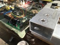
There is a double row of holes on the bottom to Venturi the heat out BTW. I can add more holes if necessary. Where the plexiglass base narrows is where the holes are drilled in the bottom of each enclosure as shown.
The Trans needs its bell housing covers removed just to slide inside without cutting away
the bottom area.
The pcbs are isolated from the cases that will go to the ground pin along with the cables foil shield. It will single end connect at the earth side
Fun project overall.
Regards
David
Are you using conformal coat? How much capacitance does it contribute? The only area that is critical is around the EQ section which I would recommend you not coat, plus you may want to make changes later on if I come up with a better EQ down the road.
A couple of slots above the heat sinks should provide good convection over the sinks based on what you describe.
A couple of slots above the heat sinks should provide good convection over the sinks based on what you describe.
Funny you mention that..,
The other photo upside down pc. had this on it 😎
I am not anodizing (best of course) just using an Aluminprep mild acid and lite Alodine for corrosion and then outside coating of clear.
I was a licensed Airframe & Powerplant FAA mechanic many many moons ago and worked on small business jets and now retired, and used to mess with alum. all the time way back in the day.
So there is no issue on grounding or getting thru to the raw material.
Regards
David
Attachments
Ah, I think I misread or misinterpreted what you wrote, I thought you were talking about coating the PCB not the aluminum. 
It looks great. And I see you have made provisions for additional ventilation as suggested.
Based on looking at this I have decided to put my breadboard unit in three boxes as you are doing. (I did this in the original Muscovite as well so there is precedent)
I see you got the end bells off the transformer OK, are you going to mount it on standoffs? I would make them three of them non-conductive with insulated washers on both sides and a sleeve of some sort inside in order to minimize currents through the core and chassis unless it is mounted on plexiglas in which case do ground the core at one point in addition to the electrostatic shield.
In long term use you will want to clamp the core (bolts and washers) regardless of how you mount it in order to prevent the laminations from loosening up and buzzing. The one running in my supply is extremely quiet and not audible from even a foot or so away in normal use.
The PSU and transformer also dissipate some power with the filament regulator (about 5W typical) and rectifier (probably 5W!) being the most. Again something north of 15W total depending on line voltage..
The mosfets are dissipating at most 2W and likely a bit less between them at typical line voltages.
VTA
As far as I can tell with the Bliss replacement stylus tail up by some number of degrees seems optimum.
The general wisdom seems to be that the cartridge top should be parallel with the record surface which doesn't seem to be the case with these.
Listening is by far the best indicator, the least distortion in the highs and smoothest midrange response is clearly the direction to head.
Get it off a bit and there are hints of harshness on some material, and it gets more strident the further off you are, fairly obvious you'd think. It also affects the cartridge's tonal balance adversely.
Yes, the trans is just sitting there for now , I will stand off the trans and bolt the cores together. Didn,t think about grounding on one of the bolts and good info.
From what you say about the compliance and tracking force, this plastic body and the way the cantilever detaches, it just screams to be rebuilt in a more rigid fashion overall. Sound smiths remake seems logical. They have adjutment screws on the side also.
From what I can see, they redo the Panasonic,s design and not Win,s
I would even imagine a way to make a moveable cantilever/ donut position on the beams of the strain gauge to vary all forces.
If Win excites the ends of the beams at lower tracking forces (more leverage) less gain? Then it would interesting to see the difference of the 450/451 vs the 460/465 in where on the beams they push in comparison to each other to explain the tracking force requirements. ? Don,t know
if I can find another cartidge it will be gutted and remounted in an open arrangement with the body made similiar to the Lyra,s with copper or brass inserts and a strong bolted adjustable cantilever system.
Should be doable and fairly straight forward in comparison to a MC that isn,t even possible.
Regards
David
Good thoughts all, I believe that the compliance is controlled by the damper assembly in the cartridge, I have a 451C and a 465C and the active area of the transducer is the same in both cases, but tracking force required and compliance are not. Both are otherwise very similar in performance.
During the pre-amp design phase** I actually had two 451C, a 460C and a 465C. The 450CII is similar but has the highest compliance and lowest tracking force requirements.
The 450C is an entirely different strain gauge based design with significantly poorer performance in terms of frequency response deviations.
You are correct that the Sound Smith is not based on the Win design.
I would be most interested in what you come up with in terms of a modified cartridge, you are on the right track.
** There are 3 generations of pre-amp design, the very first was scrapped to make way for the 2nd generation. The released design (2.1a) is a slightly improved version of the 2nd generation design.
In the future I may try to determine whether it is possible to further improve the EQ. This would be located on a small plug in card that plugs into the 4 pin connector currently used to set the gain. I don't see any other major changes to this design in the future. I do recommend leaving enough room for output transformers in case in the future you want to use them for balanced output and/or phase inversion between the channels.
The BOM recommendations are good middle of the road in terms of cost/performance ratio, I do like REL TFT and Vcap TFTF even better than the RTX, but was not sure the expense was justifiable in this application. It is a judgment call, and I think at the point of diminishing returns.
The BOM recommendations are good middle of the road in terms of cost/performance ratio, I do like REL TFT and Vcap TFTF even better than the RTX, but was not sure the expense was justifiable in this application. It is a judgment call, and I think at the point of diminishing returns.
No, I would not recommend that at all. Depending on where they are being used noise and distortion could increase. You can use other brands besides Panasonic, you can also go to tighter tolerance in some cases.
What parts can you not find? If you list them here I may be able to provide an alternative DigiKey part number that is suitable. (Friday sometime)
What parts can you not find? If you list them here I may be able to provide an alternative DigiKey part number that is suitable. (Friday sometime)
- Home
- Source & Line
- Analogue Source
- Playing With Panasonic Strain Gauge Cartridges (And A Dedicated Phono Stage)