The LSK389 is available here:
LSK389C SOIC 8L | Linear Integrated Systems | Trendsetter Electronics
Make sure you get the bin C part. i.e. LSK389C
LSK389C SOIC 8L | Linear Integrated Systems | Trendsetter Electronics
Make sure you get the bin C part. i.e. LSK389C
Cartridges and Arms
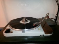
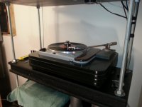
I have a 451C mounted on a custom arm wand on the Souther Tri-Quartz, it sounds pretty good most of the time but still suffers from insufficient mass that results in mis-tracking on dubstep and electronica on some very bass heavy passages.
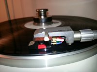
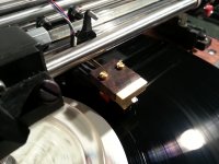
I have the 465C mounted on an 18gm Audio Technica with a rosewood spacer that adds about another gm plus the 3.5gms of the cartridge. This provides sufficient mass that I can balance the arm and barely set the tracking force to the 4gms recommended.
The beautiful little Jeweltone is completely incompatible with the Schick, just to late - so I will save it for use on another arm.
The 451C seems happier towards 3gms on the LTA where it lives.
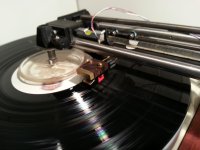
The 465C on the Schick as described above is about as good as it gets with these cartridges. The Windfeld will not be going back on this table for the moment.
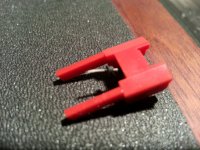
I've included a picture of the "Bliss" stylus, unprepossessing in experience it is nonetheless the real deal, and it seems quite common. This is a photo of the second one I purchased on eBay recently for $49 as a random guess. Nude shibata stylus and probably an aluminum cantilever. It is slightly better sounding overall than the NOS Panasonic QD451 I have on hand.
Can't get away from the fact that these cartridges want heavy tone arms, the compliance is very low, and perhaps even lower than new due to hardening over time of the elastomer dampers on the strain gauge transducers. (Given what happens to other cartridges I can not believe that the same thing isn't happening to these cartridges as well.)
I have a 451C mounted on a custom arm wand on the Souther Tri-Quartz, it sounds pretty good most of the time but still suffers from insufficient mass that results in mis-tracking on dubstep and electronica on some very bass heavy passages.
I have the 465C mounted on an 18gm Audio Technica with a rosewood spacer that adds about another gm plus the 3.5gms of the cartridge. This provides sufficient mass that I can balance the arm and barely set the tracking force to the 4gms recommended.
The beautiful little Jeweltone is completely incompatible with the Schick, just to late - so I will save it for use on another arm.
The 451C seems happier towards 3gms on the LTA where it lives.
The 465C on the Schick as described above is about as good as it gets with these cartridges. The Windfeld will not be going back on this table for the moment.
I've included a picture of the "Bliss" stylus, unprepossessing in experience it is nonetheless the real deal, and it seems quite common. This is a photo of the second one I purchased on eBay recently for $49 as a random guess. Nude shibata stylus and probably an aluminum cantilever. It is slightly better sounding overall than the NOS Panasonic QD451 I have on hand.
Can't get away from the fact that these cartridges want heavy tone arms, the compliance is very low, and perhaps even lower than new due to hardening over time of the elastomer dampers on the strain gauge transducers. (Given what happens to other cartridges I can not believe that the same thing isn't happening to these cartridges as well.)
Attachments
Thanx for the information on the tip , Kevin.
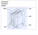
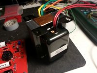
BTW , Do you have the dimensions for the Heyboer trans ?
Also can someone please tell me what a clear top measures on width? An RCA/Sylvania measures .800"/20mm for example and know the cleartops are bigger dia.
Drilling a couple of holes and want the ability to swap both versions.
Regards
David
BTW , Do you have the dimensions for the Heyboer trans ?
Also can someone please tell me what a clear top measures on width? An RCA/Sylvania measures .800"/20mm for example and know the cleartops are bigger dia.
Drilling a couple of holes and want the ability to swap both versions.
Regards
David
Mucho News
The Heyboer transformers arrived today, and I will start to ship this week-end. It will take me about a week to ship them with all the boards +/-.
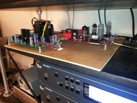
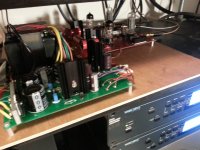
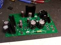
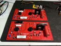
I fired up the Rev2.1 boards and power supply and am happy to report things are working pretty much as expected.
The current subtraction is a little too efficient and we may have to make minor adjustments in a single resistor value to compensate depending on the specific fets you have. I will advise - fortunately these are inexpensive SMD resistors.
The one other thing is the filament bridge rectifier runs rather warm, I recommend a small heat sink or alternately a set of 4 Schottky diodes wired on a small board to fit the pin out.
I am happy to report that the pre-amp is extremely quiet. The solid state supply significantly outperforms the wonky tube supply powering the other unit.
The Heyboer transformers arrived today, and I will start to ship this week-end. It will take me about a week to ship them with all the boards +/-.
I fired up the Rev2.1 boards and power supply and am happy to report things are working pretty much as expected.
The current subtraction is a little too efficient and we may have to make minor adjustments in a single resistor value to compensate depending on the specific fets you have. I will advise - fortunately these are inexpensive SMD resistors.
The one other thing is the filament bridge rectifier runs rather warm, I recommend a small heat sink or alternately a set of 4 Schottky diodes wired on a small board to fit the pin out.
I am happy to report that the pre-amp is extremely quiet. The solid state supply significantly outperforms the wonky tube supply powering the other unit.
Attachments
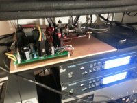
No, just supported by the one rectifier, there are several hundred mils of clearance to the fuse holder. This was an expedient just to keep the rectifier from getting excessively hot.
I would definitely recommend a small finned heat sink on that rectifier. Other things to consider would be a chassis mounted rectifier, the standard 12 - 25A versions would be fine, or a vector board stuffed with some >3A Schottky diodes, that would provided the added benefit of a little more regulator headroom particularly for low line conditions.
Some comments on subjective performance are in order. With the solid state supply it is significantly quieter than with the tube based regulated supply.
The changes between the prototype rev2.0 and the rev2.1 boards that everyone is getting is the addition of support for external EQ later on if I figure out any improvements, and incorporating the current subtraction CCS rework into the board design and adding a pot to allow some tweaking of the current for matching. I rearranged the filament connections a bit to eliminate a via with a lot of current flowing through it.
It's a very detailed and yet pleasant listening experience. The combination of cartridge and pre-amp is probably the cleanest sounding I have heard in my system until the cartridge gets into trouble, and as I get better at figuring how to keep the cartridge happy this becomes more and more infrequent. The complete lack of sibilance on highs is an immense relief for someone who has suffered through that with a Windfeld and few other cartridges. There are those audiophile thingies they like to talk about too..
Package Shipping Status
I was able to ship almost all of the kits this morning except those for:
super10018 and Atom666
Guys, I will let you know here when your packages ship.
If your name is not on the list your package is on the way.
I ran out of packing materials (more acquired today) time and energy, the last two packages will be packed tonight and will ship sometime early in the new week.
I had promised to ship everything by next week-end and it looks like I will beat that handily.
Please let me know your package arrived safely either here or by email.. Thanks!

Change List PSU
PSU:
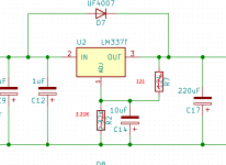
-24V Bias Regulator
Change R7 from 124 ohms to 121 (1206 SMD)
Change R2 from 2.32K to 2.21K (RN60)
C12 is a 1uF 63V PP metalized film.
Purpose: This reduces the slightly high bias supply from a touch over 25V to the target 24V.
Tolerance of supply should be <= +/- 4% with typical LM337
This change can be considered optional, but worthwhile if you have not already built the supply.
AC Primary Side:
Note I recommend a 1.0A MDL fuse for primary protection, which should be placed before the power switch on the line side of the AC connection.
A safety earth must be provided and connected directly to the metal chassis, and the power transformer electrostatic shield. (orange lead)
The PSU common (noting that the filament supply floats!) should be connected through a 10 ohm 2W resistor in parallel with a pair of 1N5408A diodes in an anti-parallel connection (anode to cathode) to the safety earth.
Transformer Color Codes:
Black - Primary
Red - HV secondary
Yellow - Filaments
Green - Bias
Orange - Electrostatic shield
Filament Supply
The GBU6B MUST be fitted with a heat sink, it will otherwise run too hot. (20C/W or less thermal resistance will be fine.)Alternatives would include not installing a rectifier on the board and using a chassis mounted such as this one:
GBPC12005-E4/51 Vishay Semiconductor Diodes Division | Discrete Semiconductor Products | DigiKey
The other alternative is to build a small bridge on perf board using these:
SB530-E3/54 Vishay Semiconductor Diodes Division | Discrete Semiconductor Products | DigiKey
They will run hot so space them well off of the board.
C13 is a 1uF 63V PP metalized film cap.
General Comments:
Please build as designed to assure reasonable reliability.
Do not overheat SMD regulators, I recommend pre-heating the PCB with a hair drier or heat gun before installing the LR8K4-G and LM337T.
Solder the heat sinks in place after all the SMD parts are installed and you are ready to install the LT1085 and IRF820s.
Verify that there are no shorts between the tab (drain) of each mosfet to the grounded heat sink BEFORE you solder. There will be 340 - 350V present on the device tabs when operating so make sure there is no way the hardware can short to the heat sink. I doubled up on the silpads on mine.
I recommend installing C20 and C21 after everything else.
Assume that the LR8K4-G, IRF- 820 and LM337T are static sensitive sensitive and treat accordingly.
SAFETY:
HAZARDOUS voltages are present in this design when operating and for some time after power is removed.
The raw HV voltage is approximately 340V - 350V, and the input filter capacitors will hold charge for a period of time after the unit is shut off.
Do not work on or trouble shoot if you are tired or otherwise impaired.
Bring Up:
The output voltage is approximately +300V in operation. Typical voltages under load should range from 295 - 305V and should be extremely stable at full line voltage under load.
At first power up I recommend a variac and careful measurements starting at intervals of 20V or so as you increase the voltage. A 100V ballast lamp will prevent serious damage to the transformer and at least some of the circuitry on the regulator card.
Undetected shorts on the board will likely result in the instantaneous destruction of the related semiconductors in the HV supply.
I would either use the phono pre-amps as a load (having checked them for shorts first) and with tubes installed OR a pair of 25W 15K power resistors. Be cautious, accidental contact with these voltages is hazardous, and a short may result in a mosfet grenading.
PSU:
-24V Bias Regulator
Change R7 from 124 ohms to 121 (1206 SMD)
Change R2 from 2.32K to 2.21K (RN60)
C12 is a 1uF 63V PP metalized film.
Purpose: This reduces the slightly high bias supply from a touch over 25V to the target 24V.
Tolerance of supply should be <= +/- 4% with typical LM337
This change can be considered optional, but worthwhile if you have not already built the supply.
AC Primary Side:
Note I recommend a 1.0A MDL fuse for primary protection, which should be placed before the power switch on the line side of the AC connection.
A safety earth must be provided and connected directly to the metal chassis, and the power transformer electrostatic shield. (orange lead)
The PSU common (noting that the filament supply floats!) should be connected through a 10 ohm 2W resistor in parallel with a pair of 1N5408A diodes in an anti-parallel connection (anode to cathode) to the safety earth.
Transformer Color Codes:
Black - Primary
Red - HV secondary
Yellow - Filaments
Green - Bias
Orange - Electrostatic shield
Filament Supply
The GBU6B MUST be fitted with a heat sink, it will otherwise run too hot. (20C/W or less thermal resistance will be fine.)Alternatives would include not installing a rectifier on the board and using a chassis mounted such as this one:
GBPC12005-E4/51 Vishay Semiconductor Diodes Division | Discrete Semiconductor Products | DigiKey
The other alternative is to build a small bridge on perf board using these:
SB530-E3/54 Vishay Semiconductor Diodes Division | Discrete Semiconductor Products | DigiKey
They will run hot so space them well off of the board.
C13 is a 1uF 63V PP metalized film cap.
General Comments:
Please build as designed to assure reasonable reliability.
Do not overheat SMD regulators, I recommend pre-heating the PCB with a hair drier or heat gun before installing the LR8K4-G and LM337T.
Solder the heat sinks in place after all the SMD parts are installed and you are ready to install the LT1085 and IRF820s.
Verify that there are no shorts between the tab (drain) of each mosfet to the grounded heat sink BEFORE you solder. There will be 340 - 350V present on the device tabs when operating so make sure there is no way the hardware can short to the heat sink. I doubled up on the silpads on mine.
I recommend installing C20 and C21 after everything else.
Assume that the LR8K4-G, IRF- 820 and LM337T are static sensitive sensitive and treat accordingly.
SAFETY:
HAZARDOUS voltages are present in this design when operating and for some time after power is removed.
The raw HV voltage is approximately 340V - 350V, and the input filter capacitors will hold charge for a period of time after the unit is shut off.
Do not work on or trouble shoot if you are tired or otherwise impaired.
Bring Up:
The output voltage is approximately +300V in operation. Typical voltages under load should range from 295 - 305V and should be extremely stable at full line voltage under load.
At first power up I recommend a variac and careful measurements starting at intervals of 20V or so as you increase the voltage. A 100V ballast lamp will prevent serious damage to the transformer and at least some of the circuitry on the regulator card.
Undetected shorts on the board will likely result in the instantaneous destruction of the related semiconductors in the HV supply.
I would either use the phono pre-amps as a load (having checked them for shorts first) and with tubes installed OR a pair of 25W 15K power resistors. Be cautious, accidental contact with these voltages is hazardous, and a short may result in a mosfet grenading.
Attachments
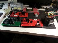
Change List: Audio PCB (V2.1A)
There are a number of minor changes/recommendations and guidelines provided here.
First, the pre-amp should not be run without either a Panasonic strain gauge cartridge connected, or a pair of 1K load resistors on the inputs. There is a very slight possibility doing so could damage the LSK389. (I have tested this and have seen no instance where that could happen, but...)
Filaments:
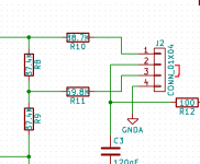
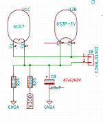
Install C8 on one PCB only. I currently recommend 47uF/63V this reduces residual effects of transformer leakage currents (not much with the heyboer transformers, but a big problem with transformers without electrostatic shielding)
Use tightly twisted wires to connect the filaments to the supply.
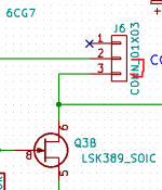
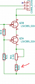
Current Subtraction CCS:
Jumper J5 pins 2 & 3
Jumper J6 pins 2 & 3
The CCS can be disabled by removing both jumpers, but I do not recommend this mode of operation as it slightly compromises the linearity of the first stage. (Basically operating at 1/2 of the current)
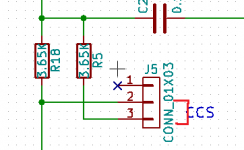
To set the operating current to the cartridge it is sufficient to assure the current is between 3.5 - 4.0mA.
Install a 1K resistor across each input, and connect a DVM across it.
At first power up you should observe the voltage drop to - 500mV to -600mV (if it goes more negative you may have installed the diode D1 the wrong way around or omitted it), then rapidly increase to some positive value, once it stabilizes adjust both channels so that they have identical voltages somewhere in the +3.5V to 4.5V range. (Note that a 10% difference should result in about a 1dB difference in output between the channels. Cartridge resistances seem well matched, but may change significantly as the cartridge warms up - the pre-amp is designed to accommodate these changes in cartridge resistance)
If you are highly motivated and don't mind experimenting a bit you may find adjusting the value of R20 to move the range of benefit. (This is highly FET dependent so I cannot give you an exact value.)
The CCS subtracts current so to increase current through the cartridge increase the value of R20 to reduce the current through the CCS slightly.
To reduce current through the cartridge (because it is still too high and you have run out of adjustment range) reduce the value of R20.
I do not recommend less than 4.99K or more than 6.49K.
You wonder why I did not use a higher value pot, the reason was concerns about drift over time and temperature. Changing RV1 to 2.0K is probably OK, but I have not tried it.
Gain:
I recommend installing the jumper between J2 pins 2 & 3, this provides sufficient gain for almost any situation, if you wish to run higher gain, 6dB of additional gain is available by jumpering 1 & 2 instead.
EQ:
J2 is intended to provide an option for more complex EQ should I decide to pursue something more complex in the future.
The current EQ in arm with a 451C manages better than +/- 3dB from 20Hz - 20kHz with pink noise measurements which is comparable to a good vintage LOMC.
J2 Pin 2 should not be grounded or left open, this leaves the 6S3P without bias, current is limited by the cascode CCS to about 10mA, but the CCS in one scenario will dissipate about twice the normal dissipation and the heat sink will get hot. In the other scenario the voltage developing across the 6S3P could result in arcing resulting in the destruction of both the tube, CCS, and possibly the power supply. Or nothing will happen as is most likely the case.
Inputs:
Each channel of the cartridge gets its own fully independent set of connections, which must float. Do not connect either input to anything but the PCB ground provided for the purpose.
Output and power grounds may be run to a common point. I have not had problems with using the audio ground on each board to the respective output RCA jacket. The power ground should in any case go to a common point and be connected to the chassis at one point.
The PSU ground should be connected to safety earth through a 10 ohm resistor and pair of anti-parallel 1N5408A diodes.
There are a number of minor changes/recommendations and guidelines provided here.
First, the pre-amp should not be run without either a Panasonic strain gauge cartridge connected, or a pair of 1K load resistors on the inputs. There is a very slight possibility doing so could damage the LSK389. (I have tested this and have seen no instance where that could happen, but...)
Filaments:
Install C8 on one PCB only. I currently recommend 47uF/63V this reduces residual effects of transformer leakage currents (not much with the heyboer transformers, but a big problem with transformers without electrostatic shielding)
Use tightly twisted wires to connect the filaments to the supply.
Current Subtraction CCS:
Jumper J5 pins 2 & 3
Jumper J6 pins 2 & 3
The CCS can be disabled by removing both jumpers, but I do not recommend this mode of operation as it slightly compromises the linearity of the first stage. (Basically operating at 1/2 of the current)
To set the operating current to the cartridge it is sufficient to assure the current is between 3.5 - 4.0mA.
Install a 1K resistor across each input, and connect a DVM across it.
At first power up you should observe the voltage drop to - 500mV to -600mV (if it goes more negative you may have installed the diode D1 the wrong way around or omitted it), then rapidly increase to some positive value, once it stabilizes adjust both channels so that they have identical voltages somewhere in the +3.5V to 4.5V range. (Note that a 10% difference should result in about a 1dB difference in output between the channels. Cartridge resistances seem well matched, but may change significantly as the cartridge warms up - the pre-amp is designed to accommodate these changes in cartridge resistance)
If you are highly motivated and don't mind experimenting a bit you may find adjusting the value of R20 to move the range of benefit. (This is highly FET dependent so I cannot give you an exact value.)
The CCS subtracts current so to increase current through the cartridge increase the value of R20 to reduce the current through the CCS slightly.
To reduce current through the cartridge (because it is still too high and you have run out of adjustment range) reduce the value of R20.
I do not recommend less than 4.99K or more than 6.49K.
You wonder why I did not use a higher value pot, the reason was concerns about drift over time and temperature. Changing RV1 to 2.0K is probably OK, but I have not tried it.
Gain:
I recommend installing the jumper between J2 pins 2 & 3, this provides sufficient gain for almost any situation, if you wish to run higher gain, 6dB of additional gain is available by jumpering 1 & 2 instead.
EQ:
J2 is intended to provide an option for more complex EQ should I decide to pursue something more complex in the future.
The current EQ in arm with a 451C manages better than +/- 3dB from 20Hz - 20kHz with pink noise measurements which is comparable to a good vintage LOMC.
J2 Pin 2 should not be grounded or left open, this leaves the 6S3P without bias, current is limited by the cascode CCS to about 10mA, but the CCS in one scenario will dissipate about twice the normal dissipation and the heat sink will get hot. In the other scenario the voltage developing across the 6S3P could result in arcing resulting in the destruction of both the tube, CCS, and possibly the power supply. Or nothing will happen as is most likely the case.
Inputs:
Each channel of the cartridge gets its own fully independent set of connections, which must float. Do not connect either input to anything but the PCB ground provided for the purpose.
Output and power grounds may be run to a common point. I have not had problems with using the audio ground on each board to the respective output RCA jacket. The power ground should in any case go to a common point and be connected to the chassis at one point.
The PSU ground should be connected to safety earth through a 10 ohm resistor and pair of anti-parallel 1N5408A diodes.
Attachments
Further thoughts
I hope the above is enough to get you all launched.
I tend to prefer placing the power supply in one chassis and the audio circuitry in another.
I prefer inexpensive CPC type connectors that you can purchase from DigiKey. I generally use gold contacts and hand crimp and solder each connection before insertion. I like teflon wire in an expandable mesh tubing.
The transformer in my 2.1a prototype is in close proximity to everything else and it's very quiet so I suppose you could mount it all in one box if you wanted to. The transformer should be placed at least six inches from the output circuitry and as far away from the inputs as can be managed - same for the rectifier end of the PSU board.
For those even crazier than I you could mount the whole thing in three narrow boxes with two separate umbilicals feeding the pre-amp boxes.
Do not scrimp on the coupling capacitors or resistors in the audio path. I have done a lot of cost cutting in this design to keep costs down, by spending the money where it counts. Many of the parts can come straight from DigiKey, needless to say that does not include those caps or resistors. It pains me to say this but they really do make a difference, and I have mostly avoided the insane end of the spectrum. Good film caps are not cheap.
All SMD resistors should be thin film for linearity and noise reasons. Panasonic are a particular, err, favorite..
Some Japanese 6CG7 (in addition to all the usual suspects) seem to perform well in this circuit, and in terms of 6S3P you can try them all, but I would avoid the DR, contrary to expectation it has the largest variation in mu sample to sample, and IMHO is the worst sounding variation.
Most of all have fun, and expect to work to discover the potential of these cartridges, which is considerable. I am still working on this, and I am sure I am not fully down that road by a long shot, so be patient and learn to make the cartridge work for you.
Remember these cartridges are ridiculously low compliance, cheaply housed devices with terrible resonances if you are not careful and benefit tremendously from any effort you make to address these issues.
Use the heaviest arm you can get your hands on, mount it on a heavy head shell, wood seems to help a lot in the upper octaves, whether a shell or spacer.. They really need spacers in most cases.
Track somewhere near the top of the recommended force range for the cartridge in use.
The 451C seems happy above 2.5gms, and I generally run it around 2.8gms. Compliance is about 25% higher than the 460/465.
The 460/465C are not happy significantly below 4gms, and I run my 465C at 4 - 4.2gms on the Schick, this is in the same range as the SPU GM II and GM E II.
Record life as long as you maintain the cartridge properly and keep records reasonably clean is fine. I have many records from my teen years that were played hundreds if not thousands of times with cartridges tracking at 4gms or greater. They are no worse than much newer records played at somewhat to considerably lower tracking forces for a comparable number of times.
Finally remember that these cartridge have outputs that invert phase one channel relative to the other, remember at minimum to reverse polarity at (just) one speaker in your system if you do not have provisions elsewhere in your system to do so. 1:1 transformers (parafeed) are another option and allow for balanced output if you want it.
Wow, that's really snazzy!
I would recommend a little ventilation around the cascode CCS heat sink.. Maybe a slot either side of the center line of the heat sink, and some slots along the sides. (They can be quite small, convection should work well as long as air can get in.)
Cascode CCS dissipation is only around 1.5W, which should result in a rise of about 10C above ambient with the heat sink fitted, but it will heat the ambient air inside the box as will the tubes which are producing much more heat. One channel is dissipating around 10W total.
I would also make sure the case is grounded so that it provides shielding to the internal electronics, which does not seen terribly sensitive to external pick up based on experience with my breadboard.
- Home
- Source & Line
- Analogue Source
- Playing With Panasonic Strain Gauge Cartridges (And A Dedicated Phono Stage)