you just need to go to Miller Audio Research where you can click and send a registration email. Annoying, but Pauls measurements so he sets the rules.
you just need to go to Miller Audio Research where you can click and send a registration email. Annoying, but Pauls measurements so he sets the rules.
The button does not execute the mailto: command on either Chrome or Explorer for me. Does it work if I copy the instructions by hand?
Does someone has any experience with Adjust+ from Dr Feickert.
Dr.Feickert::Adjust+
Adjust+ combines test software plus an LP with test tracks.
With my Benz LP I got the frequency response recording below.
I have no idea why at the upper end the response is going up and down, maybe because modulation is quite strong ?
Hans

Dr.Feickert::Adjust+
Adjust+ combines test software plus an LP with test tracks.
With my Benz LP I got the frequency response recording below.
I have no idea why at the upper end the response is going up and down, maybe because modulation is quite strong ?
Hans
http://www.milleraudioresearch.com/download2009/reports/aug09/benz_micro_lps_mc.html
You can compare. No idea about your measurement. The Fieckert test LP is on my list to obtain though.
You can compare. No idea about your measurement. The Fieckert test LP is on my list to obtain though.
http://www.milleraudioresearch.com/download2009/reports/aug09/benz_micro_lps_mc.html
You can compare. No idea about your measurement. The Fieckert test LP is on my list to obtain though.
Thank you for the link
Hans
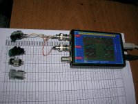
Now I have a digital signal generator and I can repeat the measurements in a much more consistent way and I will go higher in frequency.
Here is manual spot freq test and Auto frequency sweep (flat freq input, flat frequency processing. No RIAA pre-emphasis/ de-emphasis)
In both cases each cartridge is connected in series to a 50 Ohm signal generator and to the detector with a loading of 47KOhm//220pF. Interconnecting wire is 6cm twisted pair with a few pf capacitance. Detector input is1MOhm//47pF.
All measurements shown are with cartridges on air.
I’ve done many more detailed frequency sweeps on all the cartridges while touching the needle and the cantilever with my finger. No observed difference from the on air sweeps.
On the Stanton I removed the cartridge assy from the body and rerun the sweeps. Again no observed difference from the on air sweeps.
George
Attachments
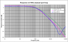
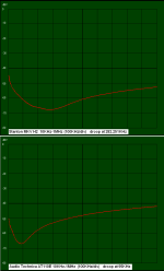
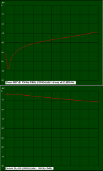
Thank you, George. It was puzzling to work out what might be going on! But looks from the photos and a quick sim to confirm like you're accidentally using a 470 ohm loading resistor rather than 47k? Plus, the loading, including the 220pf cap, is effectively in series with the coil.Here is manual spot freq test and Auto frequency sweep (flat freq input, flat frequency processing. No RIAA pre-emphasis/ de-emphasis)
In both cases each cartridge is connected in series to a 50 Ohm signal generator and to the detector with a loading of 47KOhm//220pF. Interconnecting wire is 6cm twisted pair with a few pf capacitance. Detector input is1MOhm//47pF.
All measurements shown are with cartridges on air.
I’ve done many more detailed frequency sweeps on all the cartridges while touching the needle and the cantilever with my finger. No observed difference from the on air sweeps.
On the Stanton I removed the cartridge assy from the body and rerun the sweeps. Again no observed difference from the on air sweeps.
George
As to the odd resonance, seems what you might have accidentally measured is self-resonance of the coil in association with 220pf in series and whatever strays and self C are in parallel. Whereas, in reality, the topology is different, and all strays and loading C appear across the coil, so generator resonant f is far lower.
Nevertheless, interesting, particularly for the Shure cart where self resonance appears c 40kHz or so.
To 'repair' the topology, I think it may be necessary to unground the signal generator and measure directly across the coils. At present, you're measuring across the series loading, which might not be the intention.
LD
Last edited:
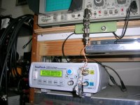
What I (almost) see as the load resistor is Yellow-Purple-Red which is 47K ??Thank you, George. It was puzzling to work out what might be going on! But looks from the photos and a quick sim to confirm like you're accidentally using a 470 ohm loading resistor rather than 47k? Plus, the loading, including the 220pf cap, is effectively in series with the coil.
As to the odd resonance, seems what you might have accidentally measured is self-resonance of the coil in association with 220pf in series and whatever strays and self C are in parallel. Whereas, in reality, the topology is different, and all strays and loading C appear across the coil, so generator resonant f is far lower.
Nevertheless, interesting, particularly for the Shure cart where self resonance appears c 40kHz or so.
To 'repair' the topology, I think it may be necessary to unground the signal generator and measure directly across the coils. At present, you're measuring across the series loading, which might not be the intention.
LD
Measuring across the load is complementary to measuring on the coil. Vcoil= Vgen-Vload so to my opinion it makes no difference where to measure, so ungrounding the signal generator wouldn't make sense.
If this is the topology used, I do not see any problem.

Thank you Lucky and Hans.
The bloody resistor is 4.7K (yellow-purple-red). My eyes betrayed me.
I will run some of the tests again with 47K probably on Monday.
As for the way of jig wiring, the intend was to monitor the voltage across the loading elements, like Hans schematic.
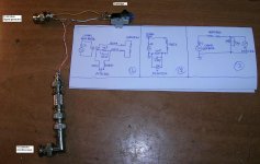
Please see attached photo and commend.
No.3 should be the electrical equivalent of No.2.
No.2 should be the electrical equivalent of No.1.
No.1 is the drawing of the physical wiring as shown on the left.
The grounding is on the oscilloscope side. The signal generator is floating.
George
The bloody resistor is 4.7K (yellow-purple-red). My eyes betrayed me.
I will run some of the tests again with 47K probably on Monday.
As for the way of jig wiring, the intend was to monitor the voltage across the loading elements, like Hans schematic.
Please see attached photo and commend.
No.3 should be the electrical equivalent of No.2.
No.2 should be the electrical equivalent of No.1.
No.1 is the drawing of the physical wiring as shown on the left.
The grounding is on the oscilloscope side. The signal generator is floating.
George
Attachments
Yes, the 4.7k explains the roll-off. Oh well, at least you found it.Thank you Lucky and Hans.
The bloody resistor is 4.7K (yellow-purple-red). My eyes betrayed me.
I will run some of the tests again with 47K probably on Monday.
As for the way of jig wiring, the intend was to monitor the voltage across the loading elements, like Hans schematic.
Please see attached photo and commend.
No.3 should be the electrical equivalent of No.2.
No.2 should be the electrical equivalent of No.1.
No.1 is the drawing of the physical wiring as shown on the left.
The grounding is on the oscilloscope side. The signal generator is floating.
George
One mystery solved, one to go......!
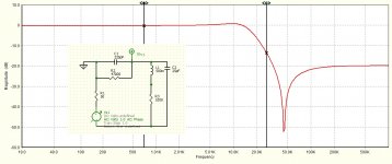
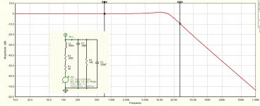
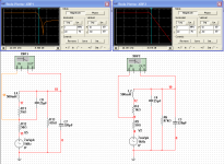
The resonance is very probably due to where you have the detector in the circuit. Attached are two plots inset with circuits: the first is as you have it, and includes 25pf for coil self C and strays. The second is more conventional and, I think reflects reality of where the voltage source and detector are during playback, in the context of the 25pf stray C.
I think you can see that the first case shows the coil self resonance, whereas the second case doesn't.
Nevertheless, it is interesting I think. As accidents can be !
LD
Attachments
Last edited:
The second is more conventional and, I think reflects reality of where the voltage source and detector are during playback, in the context of the 25pf stray C.
Now I can understand what you were meaning in the previous post. Thank you for the explanation.
I will assembly a second test jig and collect data with both test configurations.
As accidents can be !
Test bench accidents are quite frequently mind openers 🙂
George
What could possibly be the reason to measure across the Cart, what extra information would be generated by doing that ?
The other way round, when the M97 shows a dip at 40Khz while measuring across the Rload, this would implicate that the Cart has an internal parallel capacitance of 25pF.
Hans
The other way round, when the M97 shows a dip at 40Khz while measuring across the Rload, this would implicate that the Cart has an internal parallel capacitance of 25pF.
Hans
Well, I tried to build the second jig per the schematic of Lucky's post and I was short circuited. I ended up building the same circuit I already had built.
The reason is that there aren’t two approaches that can be physically implemented .
The physical difference between the two is fictitious.
The difference only exist in the world of simulation, i.e. where to connect the coil’s self capacitance of 25pF.
It is not immediately obvious but after taking the pencil and doing the rearrangement of the components on a paper, if we delete the coil’s self capacitance of 25pF, the two circuits end to be exactly the same, including the detector’s pick up point.
If we introduce the coil’s self capacitance of 25pF, at the first schematic of post #253, the 25pF capacitor is connected across the coil’s inductance and resistance.
At the second schematic of post #253, the 25pF capacitor is connected across the coil’s inductance, the resistance and the voltage generator.
These different options can not be realized in a test jig, as the coil’s self capacitance is part of the cartridge internal construction and can not be tapped from outside.
So let’s have the real world measurements guide us as to where the coil’s self capacitance is to be connected in the schematic for to achieve a realistic simulation.
George
Attachments
This is true, George has measured the self resonance of the coil as if it were a 2 wire inductance, give or take whatever the stray C might be associated with the rig floating grounds and all.The other way round, when the M97 shows a dip at 40Khz while measuring across the Rload, this would implicate that the Cart has an internal parallel capacitance of 25pF.
However, the issue is that the generator, physically distributed within the coil in reality, is not a seperate element. So, in reality, the 220pf/47k effectively shunts the 25pF stray C, and so the resonant f of the coil is L in parallel with 25pf + 220pf, give or take the effect of damping, and the resonance is monotonic.
This is also true.These different options can not be realized in a test jig, as the coil’s self capacitance is part of the cartridge internal construction and can not be tapped from outside.
Challenge is to stimulate the cartridge as a generator without invoking mechanical resonance, if it is there, which playback would do of course....hmmmmmSo let’s have the real world measurements guide us as to where the coil’s self capacitance is to be connected in the schematic for to achieve a realistic simulation.
No matter what one does to the coil as a 2 wire inductance, measurement will show there is a self-resonance because that is the nature of real inductors, it's real. But external parallel C shunts the internal self capacitance, so, in playback circuits, the effect of loading C is simply to modify the self-resonance which will always be monotonic. In other words, only measurements and simulations which have the 47k/220pf directly across the coil are realistic. Then, detecting across the coil will show a monotonic resonance in the classic style.
I think.....
LD
Challenge is to stimulate the cartridge as a generator without invoking mechanical resonance, if it is there, which playback would do of course....hmmmmm
Yes Lucky. What seems to happen is that connecting the signal generator in series with the cartridge, does not excite the mechanical resonance (if it is there).
Therefore where I wrote “for to achieve a realistic simulation”, I should have written “for to achieve a realistic simulation of the electric part of the cartridge.”
My bad.
George
AT440MLa shunted by 47kOhm and 141 pF in parallel
Here are some charts showing my measurements of a sacrificial Audio Technica 440MLa (only one channel works) with 47kOhm and 141pF across the input.
One chart shows impedance and phase - it looks as though resonance will occur a little above 20kHz - that's as high as I can measure.
The other chart plots both the measured impedance and the output shown in the October 2008 Miller Audio Research report on this cartridge.
- I have shown impedance relative to the 3000 Ohms recorded at 1kHz.
- Measured DCR was 801 Ohms, measured inductance at 1kHz was 460mH.
- I have assumed that the output curves plotted by Miller Research are shown relative to the 4mV output measured at 1kHz with an input velocity of 5 cm/s.
Attachments
Estimation of the current produced by the AT440MLa motor
There is very good agreement with the measured impedences if the impedance across the terminals of the AT440MLa is calculated assuming that:
By dividing the reported output voltage (the Miller Audio measurements) by the estimated impedence, the current produced by the motor of the AT440MLa can be estimated (shown in the attached chart). The vertical and horizontal scales are logarithmic.
There is very good agreement with the measured impedences if the impedance across the terminals of the AT440MLa is calculated assuming that:
- the motor has a DC resistance of 801 Ohms in series with an inductance of 460mH, and
- that the terminals are shunted by 47 kOhm in parallel with 141pF.
By dividing the reported output voltage (the Miller Audio measurements) by the estimated impedence, the current produced by the motor of the AT440MLa can be estimated (shown in the attached chart). The vertical and horizontal scales are logarithmic.
Attachments
- Home
- Source & Line
- Analogue Source
- mechanical resonance in MMs