I have a reel of the 2SK209s I've yet to open - that's good news about the consistency. I've been balking at putting together a clamshell sorting rig for Id vs. Vds for SOT-23 parts. I'll have to do it sooner or later to preserve my sanity, as I have a bunch of SOT-23 parts that won't be anywhere near as consistent.
Another way to make SOT-23 parts more amenable to sorting is to get some plated-through pad-per hole breadboard and cut it into little squares with 4 holes per square. You can then mount a SOT-23 part on 3 of the holes with bare wire leads so that you can test it as a normal leaded part. I usually use a low value 1/8W resistor as the gate lead (47-100 ohms) so that the part does not oscillate in the sorting jig. The oscillation can give you squirrelly results while you're trying to sort parts. The other alternative is to add the stopper resistor on the sorting jig. Since you are testing under DC conditions it's OK to use a 1k stopper resistor in the jig so that the DUT is quiet under all circumstances
Another way to make SOT-23 parts more amenable to sorting is to get some plated-through pad-per hole breadboard and cut it into little squares with 4 holes per square. You can then mount a SOT-23 part on 3 of the holes with bare wire leads so that you can test it as a normal leaded part. I usually use a low value 1/8W resistor as the gate lead (47-100 ohms) so that the part does not oscillate in the sorting jig. The oscillation can give you squirrelly results while you're trying to sort parts. The other alternative is to add the stopper resistor on the sorting jig. Since you are testing under DC conditions it's OK to use a 1k stopper resistor in the jig so that the DUT is quiet under all circumstances
andyr 2SK209 is also on test, 2 in parallel can act like one 2SK170
OK, so that's not a good choice.
How about the 2SK369 - still available as thru-hole, I am told?
Andy

I already have my own jig that I made up years ago. It hooks up to two DVMs, and allows me to sort n and p-channel jfets, n and p channel enhancement and depletion mode mosfets, and LEDs. Just about all of the projects you've seen from me over the years have used that jig to sort parts.
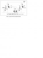
Much earlier in this thread I mused about an implementation of the classic "Pacific" circuit using readily available (at the time) devices like the J110 and J310 rather than the 2SK/LSK170. Attached is a stab at how it could be done, with cascoded gain devices and auxiliary current sources to provide extra bias current for higher gain and lower distortion. The circuit is a variant on the classic folded cascode, sort of "unfolded". The J310 is still readily available NOS from a number of sources, and of course the 2N4401 and 2N4403 are bog-standard devices available just about anywhere.
The circuit is more complex than the classic 2-device "Pacific" circuit, but the attraction would be lower distortion. Attached are the schematic from the PSpice simulation I ran, plus a response curve.
Just as a matter of interest, wrenchone, the original 'Le Pacific' circuit has the Drains of the jfets connected to the +ve DC rail (via a resistor).
AIUI, this setup removes any Miller capacitance - which is important, in the case of the 1st gain stage of a MM phono stage (otherwise this Miller capacitance would be loading the cart).
Does the 1st gain stage setup in your revised circuit (which is cascoded) also remove Miller capacitance?
I already have my own jig that I made up years ago. It hooks up to two DVMs, and allows me to sort n and p-channel jfets, n and p channel enhancement and depletion mode mosfets, and LEDs. Just about all of the projects you've seen from me over the years have used that jig to sort parts.
Nice one your jig. I have this useful thingy for SOT-23.
Attachments
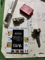
Nice one your jig. I have this useful thingy for SOT-23.
Very nice, I will buy one, thanks Salas.
@andyr
The original Le Pacific setup does not stop Miller developing by full gain.
Aah, OK, Salas ... I didn't know this.

I thought that when Drain was connected to the +ve DC rail (via a resistor which sets the gain) - see attached circuit - this setup removed Miller capacitance?
Thanks,
Andy
Attachments
No, its a classic common source arrangement.
Watch this video. You will understand.
Basics of a Cascode Amplifier and the Miller Effect
Watch this video. You will understand.
Basics of a Cascode Amplifier and the Miller Effect
No, its a classic common source arrangement.
Watch this video. You will understand.
Basics of a Cascode Amplifier and the Miller Effect
Thanks for the link to the video, Salas. Very easy to understand!
Andy
No, its a classic common source arrangement.
Watch this video. You will understand.
Basics of a Cascode Amplifier and the Miller Effect
Hi Salas,
I notice that the circuit which the guy shows in his video has the cascode as an NPN transistor sitting on top of a second NPN (so the Emitter of the top transistor is connected to the Collector of the bottom transistor).
But I have seen in other circuits, a PNP transistor sitting on top of a 2SK170 (so the Collector of the top transistor is connected to the Drain of the bottom 2SK170).
So can either a PNP or an NPN transistor be used as the cascoding transistor?
Thanks,
Andy
Yes, but a PNP must be used when the DC voltage at its collector is lower than the one's it cascodes. Liike in "folded" cascode that has the load resistor connecting to ground. My UFSP phono's input stage for instance. Which is NJFET+PNP hybrid fold. The straight to rail cascode as in the video, which is most commonly met, is also sometimes named "telescopic".
P.S.
Always emitter input on top to be a common base for cascoding. Collector to drain you saw maybe it was a constant current source load.
P.S.
Always emitter input on top to be a common base for cascoding. Collector to drain you saw maybe it was a constant current source load.
My UFSP phono's input stage for instance. Which is NJFET+PNP hybrid fold.
Can you point me to the thread about your UFSP phono stage, Salas?
I looked in "Analogue Source" but couldn't find it.
Andy
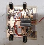
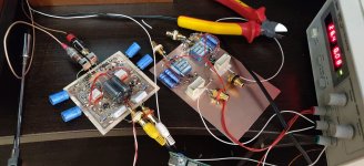
iteration next is 2x2SK209 in parallel per position. developed board, fets matched, separate g.stoppers and s. resistors per fet. pcb is done fast , in a few h, and components mounted in 3D. voltage gain is fine, 35dB, DC supply with Rs=30 ohms must be over 24V, from 28-32V.. or Rs to be increased to 40ohms and use lower DC supply (with lower total gain ). found some nos polystyrene Rifas which i will test through RIAA and coupling positions.
on first there is no big difference between this and previous version with 2SK2394.. need to make A/B switcher to find out differences fast.
on first there is no big difference between this and previous version with 2SK2394.. need to make A/B switcher to find out differences fast.
Attachments
Can you point me to the thread about your UFSP phono stage, Salas?
I looked in "Analogue Source" but couldn't find it.
Andy
In analogue source, find the simplisitc njfet riaa thread, in its post#1 there are links for its evolution phases, about UFSP is the bottom link.
iteration next is 2x2SK209 in parallel per position. developed board, fets matched, separate g.stoppers and s. resistors per fet. pcb is done fast , in a few h, and components mounted in 3D. voltage gain is fine, 35dB, DC supply with Rs=30 ohms must be over 24V, from 28-32V.. or Rs to be increased to 40ohms and use lower DC supply (with lower total gain ). found some nos polystyrene Rifas which i will test through RIAA and coupling positions.
on first there is no big difference between this and previous version with 2SK2394.. need to make A/B switcher to find out differences fast.
Nice test board work. Its for MM cartridge, yes? Because gate stoppers and highish source pin resistors contribute directly to the noise budget. Signal source impedance must be much higher than those to sufficiently swamp them.
- Home
- Source & Line
- Analogue Source
- Ultrasimple MM/MC RIAA preamp 2