This is what the 5X line buffer will look like. The 3.2V V source at the source of the ZVP3306A will actually be 2 pieces of GaAsP red led (1.6V drop apiece, low impedance). I may use PN4393 instead of J112 at the input, as I have 500 pieces of those (Vishay/Siliconix flavor).
Attachments
Actually, the shunt regulator works quite well, outputting 30.3 VDC, and drawing an unloaded current of about 300ma or so. Next up will be the line amp, as soon as I can select the input jfets. I may use J113s instead of J112s, as they are likely to have a lower Vgs for the drain current I'm contemplating using. They will be used in an output buffer for the 2nd RIAA stage as well as input for the line amp. The J113s I have are from Siliconix.
The J113s didn't work all that well, judging from the response using square wave excitation, so I selected a pair of reasonably well-matched J112s that I'll be trying this weekend. It looks like I laid out the top side of the source follower output buffer for the RIAA output stage using a mosfet with SGD pinout - I may select a pair of 2N7000s for that duty, since I just scored a bunch from Electronic Goldmine (Philips flavor - unusual). The bottom half of the follower is a current source using my tried-and-true favorite depletion mode mosfet the BSS159.
Last edited:
The selected J112s did the trick, at least on one channel. The HF compensation needs a touch more tweak - maybe 39pF instead of 33 pF. I'm not getting any output out of the other channel, even though it biases up just fine. I think a good visual inspection is in order.
Attachments
The ailing channel on my line amp has a shorted output - I need to pull the output SMB connector to figure out whether the short is there of if it is an internal board short that needs to be isolated with cuts and jumpers. I have had an internal short problem before on a PBCway board, and I had to isolate it with cuts and jump around it.
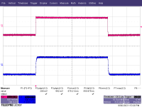
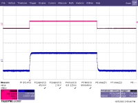
I had a look a both line amp channels today, and both look underdamped. This suggests to me that the compensation on my output probe may be out of whack, and needs tweaking (palm smacks forehead...) I'll nip in tomorrow and check that. I'll also re-adjust the comp caps on both channels for zippier response.
Attachments
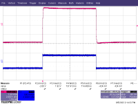
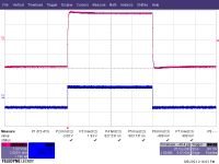
Yep - probe calibration was the problem. One I got everything dialed in on the probes, the overshoot went away. We use Probe Master probes at my place of work - a compromise between quality and affordability. One of my probes was rather cranky and erratic on the compensation adjust - that one will get replaced.
Attachments
Interesting digression.. I built Mads Circuit years ago, an Exact copy of his . It worked and continues to .. Flawlessly.
One of the best if not the best ..Phonos I've experienced .. since 1966. There may be better ones .. So what ?
I've No reason to revisit it TBH.
As small yet relevant aside;
I recently inherited a Large pile of ..New/ Unopened... Lps. Many of which were not to my tastes.
BUT I also relearned what was Common knowledge back in early 60/70's:
that By the 5th or 6th replaying of an LP..s sounds were degraded.
The sounds of my New unplayed LPs are (were") dramatically better than merely Good .
dramatically better than merely Good .
Better detail, dynamics and presence than CD playbacks by a wide margin. And massively different than Duplicate albums that I have, that have had only slight uses over the decades.
Astounding differences actually.
Vinyl can indeed be V V good, albeit while the LP is brand new or v close to it. Once even lightly worn all goodness claims are dubious.
Yess this still absolutely applies even with a decent layback gear Thorens TT / Ortofon .. in my case at least.
Devaluing all Vinyl Fanboys bleats about vinyl 'not wearing' IMO.
Gilding the playback chain 'lily' will Not restore an even barely worn plastic LP to it's former Audio glory.
What ever gets one thru their day though.
One of the best if not the best ..Phonos I've experienced .. since 1966. There may be better ones .. So what ?
I've No reason to revisit it TBH.
As small yet relevant aside;
I recently inherited a Large pile of ..New/ Unopened... Lps. Many of which were not to my tastes.
BUT I also relearned what was Common knowledge back in early 60/70's:
that By the 5th or 6th replaying of an LP..s sounds were degraded.
The sounds of my New unplayed LPs are (were
dramatically better than merely Good .Better detail, dynamics and presence than CD playbacks by a wide margin. And massively different than Duplicate albums that I have, that have had only slight uses over the decades.
Astounding differences actually.
Vinyl can indeed be V V good, albeit while the LP is brand new or v close to it. Once even lightly worn all goodness claims are dubious.
Yess this still absolutely applies even with a decent layback gear Thorens TT / Ortofon .. in my case at least.
Devaluing all Vinyl Fanboys bleats about vinyl 'not wearing' IMO.
Gilding the playback chain 'lily' will Not restore an even barely worn plastic LP to it's former Audio glory.
What ever gets one thru their day though.
Last edited:
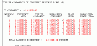
I got the jfets selected for the RIAA gain cells, and have calculated the values for the passive filter resistors, as well as selecting the EQ caps, all within 1%. Next up is dialing in the supplemental bias current sources to center the output voltage for each gain cell. I did a new layout to correct some omissions in the previous version, as well as straightening out all the reference designators - yet another build cycle - sigh... Practice makes perfect, I guess.
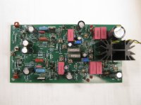
I also got the supplemental current sources tweaked for each RIAA gain cell, settling on ~14V for the output centering voltage. I used a pot to tweak in each stage, then measured the resistance of the pot afterwards. There is some drift on the current source feeding the 2nd stage, but I may be able to stabilize that by using a small heat sink on the TO-220 depletion mode fet I'm using for 2nd stage supplemental bias current.
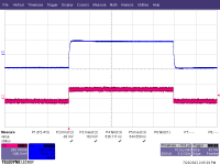
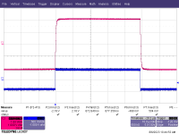
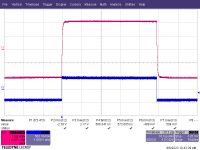
I was able to clear up the output short on the afflicted line amp channel A and get some sensible square wave response. It's a little slower in this case - I think because even though I matched the two input J112 fets for static Vgs vs. ID, the actual transconductance between the two selected fets was different. At any rate, here's what the square wave response looks like for output line amp channel A with the output short cleared out. It's actually not much slower than channel B...
Attachments
Last edited:
Next up, I'll monitor the stage voltage on the RIAA amp sections to make sure they don't drift too badly, and try to fix it if they do. The ultimate goal will be to hook up the gain-phase analyzer at work and look at the 1kHz gain to see how the two sides of the RIAA amp match up.
- Home
- Source & Line
- Analogue Source
- Ultrasimple MM/MC RIAA preamp 2