What op-amp phono preamp doesn't "suck"?
Doing an opamp circuit with good noise performance and overload margin with passive RIAA is not a trivial exercise. That's not to say it can't be done, but you have to think through gain structure very carefully, as well as input noise tradeoffs.
Let's take a simple example of an MM pre for a cartridge having 5mV nominal output at 1kHz. We would want the first gain stage to be able to get the signal out of the noise floor, so we would want at least 30dB of gain. Let's call it 32dB for ease of back-of-envelope calculation (i.e., Av = 40). We would want, at minimum, 20dB of headroom- more is better- but let's go with the marginal number to start with. So that 5mV becomes 200mV at the opamp output. That's easy. Throw in the 20dB of overload margin and we're up to a 2V swing at the output, still easy.
The turd in the punchbowl is the velocity response of the cartridge- it's 20dB per decade. So that 2V swing at 1kHz is now suddenly 20V at 10kHz and 40V at 20kHz. That will take some pretty elaborate circuitry.
So we have to use much less gain in that first stage to insure good overload performance, like 15-16dB less. Suddenly, we're facing a noise issue because the RIAA circuit is dropping the signal severely between that first and second stage and the first stage is only giving an Av of 6.
Like I said, not trivial. You could argue that there's not a lot of HF recorded on the grooves, but there's noise and mistracking which have a significant HF content. Being able to effortlessly deal with that unwanted but inevitable visitor is what separates good phono stages from "suck" phono stages.
Putting the 75us time constant in the first stage is starting to look a bit more attractive!
I seem to recall that in my phono preamp I used a first stage gain of 4, 6 or 10 followed by a passive 75us and then an active bass boost with mid-band gain of 10. Funny how the same facts lead to the same conclusions.
I saw somewhere (possibly Wireless World in the 1970s?) that someone had done some measurements and found that the signal coming off an LP (via MM) has an HF content which does not exceed the slew rate of 2.2kHz at the peak mid-band signal amplitude. I assume this would have included the effect of dust but perhaps not mistracking.
I saw somewhere (possibly Wireless World in the 1970s?) that someone had done some measurements and found that the signal coming off an LP (via MM) has an HF content which does not exceed the slew rate of 2.2kHz at the peak mid-band signal amplitude. I assume this would have included the effect of dust but perhaps not mistracking.
Thanks for the response, what you are saying makes sense. Do you have an example circuit for reference? I am trying to think of how this would be implemented by drawing blanks.Doing an opamp circuit with good noise performance and overload margin with passive RIAA is not a trivial exercise. That's not to say it can't be done, but you have to think through gain structure very carefully, as well as input noise tradeoffs.
Let's take a simple example of an MM pre for a cartridge having 5mV nominal output at 1kHz. We would want the first gain stage to be able to get the signal out of the noise floor, so we would want at least 30dB of gain. Let's call it 32dB for ease of back-of-envelope calculation (i.e., Av = 40). We would want, at minimum, 20dB of headroom- more is better- but let's go with the marginal number to start with. So that 5mV becomes 200mV at the opamp output. That's easy. Throw in the 20dB of overload margin and we're up to a 2V swing at the output, still easy.
The turd in the punchbowl is the velocity response of the cartridge- it's 20dB per decade. So that 2V swing at 1kHz is now suddenly 20V at 10kHz and 40V at 20kHz. That will take some pretty elaborate circuitry.
So we have to use much less gain in that first stage to insure good overload performance, like 15-16dB less. Suddenly, we're facing a noise issue because the RIAA circuit is dropping the signal severely between that first and second stage and the first stage is only giving an Av of 6.
Like I said, not trivial. You could argue that there's not a lot of HF recorded on the grooves, but there's noise and mistracking which have a significant HF content. Being able to effortlessly deal with that unwanted but inevitable visitor is what separates good phono stages from "suck" phono stages.
Putting the 75us time constant in the first stage is starting to look a bit more attractive!
In the design I am working with the first stage has a gain of 30.6dB while the second stage gain can vary from 27dB to 42dB. Should the first stage actually be the second stage and vice versa then?
Someone mentioned
Well actually, the RIAA filter sits between the two gain stages. Apart from rumble, the circuit and your whole setup from turntable to amplifier is more susceptible to HF noise.
Since the RIAA filter is, well, a filter, it actually filters out HF. Starting from 1 kHz and up, it dampens the signal.
With that in mind, it would be better to actually lower the gain in the first stage and make it higher in the second stage. Still, the circuit is dead quiet at 44 dB. It seems like a good compromise.
I would agree with this approach. The gain stages in this circuit are flat across the bandwidth and the equalization is done in between passively. One of the reasons for the boost of high frequencies in the recording process is to be able to drop them back down on playback, reducing the high frequency noise the stylus against the groove makes on playback. It is a better strategy (I think) to apply the higher level of gain after that has been reduced by the RIAA filtering.
What op-amp phono preamp doesn't "suck"?
http://www.diyaudio.com/forums/analogue-source/226508-openamp1-mm-phono-preamp-open-project.html
Thanks for the response, what you are saying makes sense. Do you have an example circuit for reference? I am trying to think of how this would be implemented by drawing blanks.
What I was recommending was to NOT do it that way.
 Pavel's circuit is a very good one, but it's done sensibly by not using passive RIAA. Passive is great if you have discrete devices with lots of voltage swing capability and/or perfect overload recovery, but that doesn't describe IC opamps.
Here's a write up that explored opamp based RIAA.
RIAA Equalizer Amplifier Design
Indeed, passive EQ is best suited to discrete or tube designs.
However, the active RIAA gives the best of all worlds in terms of overload margin.
For the ultimate in noise performance on MM, use a JFET front end coupled to active EQ. For a 5 mV input and 15 V rails, 36 dB overload across the audio band is achievable with 150 mV output.
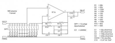
Here are two RIAA preamps with the 75us time constant in the first stage.
http://www.angelfire.com/az3/dimitri/images/riaa.pdf
Phono Pre-amp Circuit
http://www.angelfire.com/az3/dimitri/images/riaa.pdf
Phono Pre-amp Circuit
Here are two RIAA preamps with the 75us time constant in the first stage.
http://www.angelfire.com/az3/dimitri/images/riaa.pdf
Phono Pre-amp Circuit
in the schematic which I am searching for
75us was done by passive cartrige loading 6k8 resistor + cap
however those twoo are not bad
I think you are mean the Bob Cordell vinyl trak preamp. You can buy the construction article from Linear Audio.
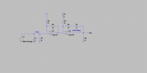
no, I have this volume for a long time, I am searching for the schematic like attached (simplified) but with the formula to calculate C1R1 knowing RLC of the cartrigde. With my limited knowledge it is hard to me to guess right loading values...
Attachments
Here's a write up that explored opamp based RIAA.
RIAA Equalizer Amplifier Design
Indeed, passive EQ is best suited to discrete or tube designs.
However, the active RIAA gives the best of all worlds in terms of overload margin.
For the ultimate in noise performance on MM, use a JFET front end coupled to active EQ. For a 5 mV input and 15 V rails, 36 dB overload across the audio band is achievable with 150 mV output.
Thanks for the good documentation! I simulated your 4 Transistor MM Amp in Fig. 4... I did not get the operating point (13 Volt at collector Q1) correct.
Gain is mutch more than the 26 dB in Fig. 6..
Are there errors in the cirucit? Is C9 correct wired?
Thanks,
Udo
- Status
- This old topic is closed. If you want to reopen this topic, contact a moderator using the "Report Post" button.
- Home
- Source & Line
- Analogue Source
- General Phono Preamp Questions