Adding variable gain control (rotary switch) and capacitance loading control (again rotary switch) to attached phono schematic. To do this I need to know the average output and ideal capacitance loading values for MM cartridges. Is 2mV-8mV and 100pf-400pF could assumptions?
For the gain control what are good dB incremendations? Is 1.5dB make sense? Based on 2mV-8mV as an assumption for cartridge output, 54dB - 42dB would be needed respectively. If I used 1.5dB increments then 8 steps would be needed.
What is the loss of the passive RIAA filter between the op-amp stages? I can calculate the gain of each op-amp but can't figure out the total circuit gain. I imagine the gain is almost constant all frequencies due to the RIAA equalization.
Finally does anyone have a part number (ideally Mouser) for a ground terminal? Ideally I'd like something like this Buy Binding Posts Ni plate brass terminal binding post,30A RS FCT021 online from RS for next day delivery.
Thanks!
Attachments
Hi, I wonder why you would bother with gain control. The loading and capacitance yes they are important. The values you show are probably fine with the addition of a zero value for capacitance. Often the cables will have sufficient capacitance and more is not needed. I didn't do the math, but a typical RIAA equalization network has a loss at 1kHZ of about 20 db. The slope is roughly 20 db of boost at 50HZ and 20db of cut at 20KHZ (a 40 db slope overall). Now back to the gain. This is a feature that is not usually needed. That is why volume controls are placed on preamps. However if you feel the need it is fairly easy to implement in IC based designs. The resistors that are switched in or out in the second stage will do the job.
Passive RIAA network has a loss of ~20dB @1kHz. MM Pre gain 40dB, MC phono pre 60dB.
I like step-up transformers.
+1 if are good.
Hi,
Your assumption about loading are ok so far.
You may like to rethink a couple of points regarding the schematics though.
Allowing for a higher than 47k input resistor is smart as high-output MMs typically feature high ohmic and inductive values in their generator coils.
This can lead to low bandwidth and a softer sound due to reduction of the highest frequency range.
Increasing the Rin may add some sparkle to the sound.
Still though I´d choose the highest resistor value wired fixed and any resistor added in parallel to this preset.
As combined resistors I´d choose 62k, 47k, 39k.
The same presetting applies to the capacitive loading (which You already sketched this way) with a fixed value, say 27pF.
For the switches I´d opt for a BCD system, either over DIP-switches or BCD rotary switches.
The cap values beeing 27pF 47pF 100pF 200pF.
As for the gain it is noisewise prefferable to put the most gain into the first stage.
The gain of the first stage must only be chosen low enough to be able to provide for sufficient headroom for clicks and pops.
the same as with the cartridge loading I´d opt for a fixed preset value of gain.
If You preset the resistor for lowest gain (as in Your sketch, the resistor going from inv to gnd)) any paralleled resistor increases gain.
So, I´d rather place the gain switch in the first stage.
But admittedly that´s not critical with MM-phono stages.
As last suggestion I´d put a 100k preloading resistor behind the output cap, from out to gnd to safely discharge the caps.
jauu
Calvin
Thanks for the answers
I am going to add the gain control for a bit more control and flexibility, changing cartridges in the future, etc.
Do my numbers 2mV-8mV and 100pF-400pF make sense? I realize most of the capacitance will be in the cables.
Unless vinyl is different now, there was no 'standard' level on LPs. LPs varied several dB from disc to disc even on the same label.
G²
A long long time ago I built a phono preamp with a couple of opamps. I made the voltage gain switchable from 40, 60, 100 times i.e. about 3dB apart. With the benefit of hindsight the x40 setting was not necessary. If I were to repeat the exercise I might use x80 and x120 instead.
Some Shure carts ouput 9.5mv and require up to 500pf. Cable cap plus your 400pf should cover that. Keep the gain control. Add selectable resistance.
Some reading about cart loading:
Cartridge loading explained - Vinyl Engine
http://www.tnt-audio.com/sorgenti/load_the_magnets_e.html
Some reading about cart loading:
Cartridge loading explained - Vinyl Engine
http://www.tnt-audio.com/sorgenti/load_the_magnets_e.html
Last edited:
Thanks for the suggestionsHi,
Your assumption about loading are ok so far.
You may like to rethink a couple of points regarding the schematics though.
Allowing for a higher than 47k input resistor is smart as high-output MMs typically feature high ohmic and inductive values in their generator coils.
This can lead to low bandwidth and a softer sound due to reduction of the highest frequency range.
Increasing the Rin may add some sparkle to the sound.
Still though I´d choose the highest resistor value wired fixed and any resistor added in parallel to this preset.
As combined resistors I´d choose 62k, 47k, 39k.
The same presetting applies to the capacitive loading (which You already sketched this way) with a fixed value, say 27pF.
For the switches I´d opt for a BCD system, either over DIP-switches or BCD rotary switches.
The cap values beeing 27pF 47pF 100pF 200pF.
As for the gain it is noisewise prefferable to put the most gain into the first stage.
The gain of the first stage must only be chosen low enough to be able to provide for sufficient headroom for clicks and pops.
the same as with the cartridge loading I´d opt for a fixed preset value of gain.
If You preset the resistor for lowest gain (as in Your sketch, the resistor going from inv to gnd)) any paralleled resistor increases gain.
So, I´d rather place the gain switch in the first stage.
But admittedly that´s not critical with MM-phono stages.
As last suggestion I´d put a 100k preloading resistor behind the output cap, from out to gnd to safely discharge the caps.
jauu
Calvin
For input loading I am going to have a 3.3M resistor hardwired then four resistors on a DIP switch; 150K, 82K, 47K and 12K. Combinations of these will give me a large range of loading options.
I will be adding a 100K pulldown on the output thanks. Probably also a ~47R series resistor too.
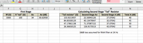
Based on MM cartridge outputs of 2mV - 8mV I figured I need between ~40dB - ~55dB of gain from my preamp. Based on these numbers I have calculated what I need the second op-amp stage "tail" resistor to be. Can someone check out my work and confirm I'm not missing something.
Attachments
Hi,
Passive RIAA with op-amps sucks by most criteria.
It is simple, but too simple IMHO. Overload is an issue.
Still, this cat can be skinned in many ways, and most
of them will work, as its a glorified integrator, and
just double slugs the input with two time constants.
rgds, sreten.
Contrary to many protestations to the contrary,
a really good RIAA stage can be very simple,
and built round one very good op-amp.
please help me find the link
Hi
Let me be slightly offtopic,
however still all about,
once in our analog source forum in some thread (unfortunately cannot remember) I followed the link to the guy
who loaded MM cartidges (probably Shure 15 mk III) with 6k8 resistor, with the cap in parallel
and this created passive 75us equalisation according to RLC values of the cartridge.
Then the signal went to good quality opamps which added further equalisation.
The author claimed that this way of loading puts the quality of MM cartiges into the ligue of MC.
Please remind me who might it be (rather famous person)?
thank you in advance!
Cartridge manufacturers design them to give a fairly flat response into a specified impedance - typically 47k in parallel with some capacitance. This usually provides some electrical compensation for the mechanical frequency response of the cartridge, as the capacitance has a heavily damped resonance with the cartridge inductance. Naively adding a heavy resistive load is not guaranteed to work. It may sound different from doing it properly, and some regard any difference as an improvement. It may also need changing if the manufacturer changes the cartridge internals.padamiecki said:who loaded MM cartidges (probably Shure 15 mk III) with 6k8 resistor, with the cap in parallel
and this created passive 75us equalisation according to RLC values of the cartridge.
Please remind me who might it be (rather famous person)?
Bob Cordell. And the noise implications were examined by Marcel van de Gevel.
Cartridge manufacturers design them to give a fairly flat response into a specified impedance - typically 47k in parallel with some capacitance.
I know about that and experienced designer of this havy load circuit too, but the benefit was worth it (if I remember correct lesser noise, flatter response curve, closer to mc cartriges, and protection from overloading next opamp with the signals of higher audio frequency).
Naively adding a heavy resistive load is not guaranteed to work.
It was geniuine, not naive
this was not stupid idea but smart and designed circuit which allowed damp 10k-15kHz peaks.
Last edited:
Bob Cordell. And the noise implications were examined by Marcel van de Gevel.
Bingo SY!
now I have only to find Marcel's circuit!
but now I think that time constant was not 75us but different...
anyway still I cannot find this schematic, btw I have linear audio vol 8.
Last edited:
Hi Mr. Positive,Hi,
Passive RIAA with op-amps sucks by most criteria.
It is simple, but too simple IMHO. Overload is an issue.
Still, this cat can be skinned in many ways, and most
of them will work, as its a glorified integrator, and
just double slugs the input with two time constants.
rgds, sreten.
Contrary to many protestations to the contrary,
a really good RIAA stage can be very simple,
and built round one very good op-amp.
What op-amp phono preamp doesn't "suck"?
- Status
- This old topic is closed. If you want to reopen this topic, contact a moderator using the "Report Post" button.
- Home
- Source & Line
- Analogue Source
- General Phono Preamp Questions