Here is another record from news station 93.8
https://www.dropbox.com/s/shgyz0wxcxfnqw5/Voice 003.m4a
I reckon the noise does sound like SMPS noise very similar to my previous usb dac which didn't take care of isolating the usb ground and audio ground...
https://www.dropbox.com/s/shgyz0wxcxfnqw5/Voice 003.m4a
I reckon the noise does sound like SMPS noise very similar to my previous usb dac which didn't take care of isolating the usb ground and audio ground...
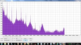
Interesting. I looked at the spectrum of that bit of silence at the start of the track and as you can see, there are definite components visible starting at 1320Hz and going up in multiples of that frequency. That is the definite "tone" you can hear. There is also a huge amount of background hash and noise.
I really don't know...
If you possibly can then try the tuner in another location (totally different address). It is still possible it could be lack of signal although those noises aren't typical of that, but they could disappear into the background with more signal and as the AGC (the RF automatic gain control) reduces the front end gain. It sounds for all the world like its picking up its own internal uP clock signals.
Attachments
I use an active indoor antenna when testing tuners, it has adjustable gain, if you overload the input of the FM4 it can make a whistling noise, the signal level indicator is fairly accurate and all but the top bar is all that is required for optimum operation. I would try an attenuator on the input, I have repaired a good few FM4s and have never had a problem with the RF sections
Stuart
Stuart
I usually don't listen much to radio when at work, but for many years, it has been more or less impossible during normal working hours. All sorts of hiss and noises. In the afternooen and evening, when most stuff is shut down, it works OK.
Back when we were operating minis and mainframes, my car radio was OK until the last 10-15m when parking close to the main building- all pops and noises only.....
Trying the tuner at a different location seems like a good idea, mainly as a test.
Back when we were operating minis and mainframes, my car radio was OK until the last 10-15m when parking close to the main building- all pops and noises only.....
Trying the tuner at a different location seems like a good idea, mainly as a test.
I had a quick look at the cct diagram (really hard to read as it was a poor copy) It look like C34 and C37 are part of the IF amplifier and will effect noise in the tuner.
±10% capacitors could give you upto 20% variation in value. Those caps are in a section where the IF is stripped from the signal. It is basically a very narrow band pass filter. It's been a long time since I repaired an FM receiver but I do remember having to re-tune when parts were replaced in the receiver section.
Have a read of this. Those capacitors are in the band pass circuit which can effect the tuning for the CF
Superheterodyne receiver - Wikipedia, the free encyclopedia
Just saw the spectrum plot and I would say the hash is almost certainly the upper and lower filters have been widened, effectively widening the band pass filter. The function of this is to remove noise and cross talk from other channels.
Have you another FM radio? tune this to the station you are listening to and see if it has the same noise if not then your antenna is OK.
Have you another FM radio? tune this to the station you are listening to and see if it has the same noise if not then your antenna is OK.
Do radio stations in Singapore broadcast "HD Radio"? The added sub-carriers and what-not for HD Radio can easily get into the audio signal. Almost all older tuners are ill-equipped to filter it. One example of what can be done is shown on the following web page in the "Modifications" section (different tuner, but the solution is likely similar if this is your problem):
Technics ST-9030
Technics ST-9030
Hi Mooly, I must apologies for the confusion. I took this record using my Samsung S4 HP. That explain the huge amount of background noise, but still, you could pick up the pitch I was referring to. Will try using direct pc mic input tonight.
Hi 405man, minimum reception I need for a listenable station is around 5-6 leds lid. Will need a proper aerial before I could provide more information.
Hi warrjon, agree the electrolyte caps are having 20% tolerance. Does it imply that the old caps are better in doing the job? On an interesting note, the C63 470nf was originally (done by Quad i think) connected to ground instead of positive lead of C34 as per schematic designed, as following mark as red:
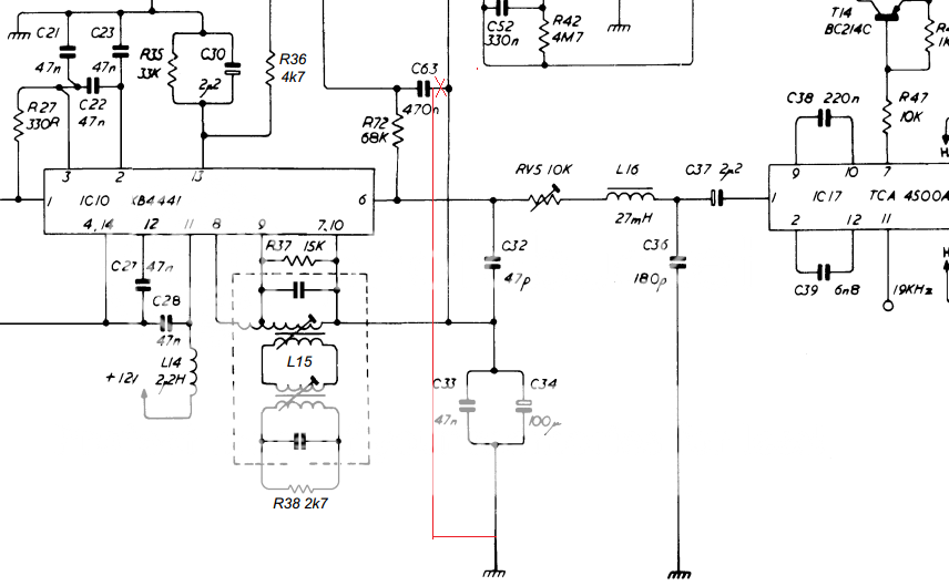
I tried to "correct" it (after experiencing the noise) by connecting the negative lead of C63 to the positive lead of C34, but it doesn't remove the noise in either configuration. I'm now very tempted to buy some high quality caps for C34 & C37 if they are the root cause of having wider band allow noise to pass through.
Hi BrainL, I don't think Singapore broadcase HD radio. The list of radio channel in Singapore is listed here: List of radio stations in Singapore - Wikipedia, the free encyclopedia
I used to own the following tuners for the past one month, with the same setup, same "wire" aerial, none of them produce this sort of "noise" problem...
- NAD 4225 (Old, approx. 30yrs old)
- Accuphase T-105 (Old, approx. 30yrs old)
- NAD C426
Unfortunately, these tuners are sold, left with Quad FM4")
Hi 405man, minimum reception I need for a listenable station is around 5-6 leds lid. Will need a proper aerial before I could provide more information.
Hi warrjon, agree the electrolyte caps are having 20% tolerance. Does it imply that the old caps are better in doing the job? On an interesting note, the C63 470nf was originally (done by Quad i think) connected to ground instead of positive lead of C34 as per schematic designed, as following mark as red:
I tried to "correct" it (after experiencing the noise) by connecting the negative lead of C63 to the positive lead of C34, but it doesn't remove the noise in either configuration. I'm now very tempted to buy some high quality caps for C34 & C37 if they are the root cause of having wider band allow noise to pass through.
Hi BrainL, I don't think Singapore broadcase HD radio. The list of radio channel in Singapore is listed here: List of radio stations in Singapore - Wikipedia, the free encyclopedia
I used to own the following tuners for the past one month, with the same setup, same "wire" aerial, none of them produce this sort of "noise" problem...
- NAD 4225 (Old, approx. 30yrs old)
- Accuphase T-105 (Old, approx. 30yrs old)
- NAD C426
Unfortunately, these tuners are sold, left with Quad FM4
Caps like C34 and C37 aren't really going to affect the tuning or alignment. C37 is simply a coupling cap and C34 bypassed by C33 provides an "AC free" point to return various circuit nodes to while allowing them to retain there DC value. Again, changing or altering the value of the cap won't alter the alignment at all. Returning C63 to ground instead of to this C34 point sounds like a typical "in production" modification. The voltage on C34 isn't a constant and perhaps it was found that some unwanted LF interaction occurred as this voltage changed and that change was coupled through C63 causing for example a "breathing" effect.
The critical critical caps are all the ones in the pf range around the coils and so on. Critical not just in value but in their physical location. If you move or bend them then the stray capacitance around them changes and so the alignment is altered.
I still think you need to try this on a different aerial at a different location first.
I tried the best place to look for aerial in Singapore. Ironically, none of the store carry fm aerial. The best I could pre order is this rh799
RH SERIES/DIAMOND ANTENNA CORPORATION
RH SERIES/DIAMOND ANTENNA CORPORATION
Last edited:
I still think you need to "prove" the tuner good at another location tbh.
An aerial like you show (2.15dbi gain) isn't enough. The dbi rating is a bit like amplifier peak music power on a good day when the mains is high The more real figure is the dbd one which just happens to the dbi figure minus 2.15db. In other words no gain.
The 3 element aerial I showed a picture of has a gain of around 7.2dbi (real gain 5dbd)
Its a massive difference in received signal level and if you really are 30km from a transmitter then you need something at least equal to that.
But try and prove all that first.
An aerial like you show (2.15dbi gain) isn't enough. The dbi rating is a bit like amplifier peak music power on a good day when the mains is high
The more real figure is the dbd one which just happens to the dbi figure minus 2.15db. In other words no gain. The 3 element aerial I showed a picture of has a gain of around 7.2dbi (real gain 5dbd)
Its a massive difference in received signal level and if you really are 30km from a transmitter then you need something at least equal to that.
But try and prove all that first.
The very high gain aerials do not bring in much more signal than a medium gain aerial.
Where they do better is at rejecting spurious signals that are off beam.
The high gain are effectively better for signal to noise, if noise is, all the other transmissions that you don't want.
Where they do better is at rejecting spurious signals that are off beam.
The high gain are effectively better for signal to noise, if noise is, all the other transmissions that you don't want.
Hi warrjon, agree the electrolyte caps are having 20% tolerance. Does it imply that the old caps are better in doing the job? On an interesting note, the C63 470nf was originally (done by Quad i think) connected to ground instead of positive lead of C34 as per schematic designed, as following mark as red:
C32,33,34,36,37 the resistor and Inductor form a narrow band pass filter. This filter will be tuned to 10.7Mhz which is the IF used in FM radio. changing these caps WILL require retuning the filter. I have had to do this many times on faulty tuners when I worked for Marantz.
I will try to explain simply how FM radios work.
Lets say you have a station at 108Mhz(F1) this is mixed (downconverted) in the mixer with a LO (Local Oscillator) 97.3Mhz (F2) frequency. The mixer produced a heap of output frequencies F1+F2, F1-F2 and a million harmonics. The frequency we are interested in is F1-F2 this is the IF and is 10.7Mhz.
BTW the LO and tuning (radio station) frequency are ganged together so F1-F2 will always = 10.7Mhz. Like if a station is 98Mhz the Lo will be 87.3Mhz = IF 10.7Mhz.
This 10.7Mhz is then amplified and goes through a narrow bandpass filter before being decoded. There is more than one stage but lets keep is simple.
The IF section is tuned to THIS (10.7Mhz) frequency if you replace a capacitor you can move the center frequency or the high and low pass filters this will allow unwanted signals into the FM decoded.
The Intermediate Frequency (IF) filter has a flattish top and very steep sides.
To get the flattish top a series of slightly different tuning frequencies are ganged together.
The precise ratio of those "slightly different tuning frequencies" is critical to getting both the flattish top and the steepness of the sides. A tiny change in one can ruin the discrimination of the passband and the stopband.
Coincidence that you chose 97.3MHz in your example.
It's the Radio station I have on now. Radio Forth ! been listening since 0730hrs on a Quad FM4.
The Intermediate Frequency (IF) filter has a flattish top and very steep sides.
To get the flattish top a series of slightly different tuning frequencies are ganged together.
The precise ratio of those "slightly different tuning frequencies" is critical to getting both the flattish top and the steepness of the sides. A tiny change in one can ruin the discrimination of the passband and the stopband.
Coincidence that you chose 97.3MHz in your example.
It's the Radio station I have on now. Radio Forth ! been listening since 0730hrs on a Quad FM4.
Absolutely correct, which is why I think changing those caps has effected the IF filter.
Last edited:
Unfortunately RF is a BLACK art. I guess the lesson is never replace components in an RF section unless it has a problem. It is different to re-Capping a PSU.
I have been repairing electronics for 35years and my motto is never fix something that is not broken.
Sorry I'll stop rambling. Back to your question. I think the easiest way would be to take it to a shop experienced with FM tuners and have them check it out. You might need to ring around as these are pretty thin on the ground now (everything is throwaway).
Yup thanks warrjon. A good lesson learnt indeed. Never mess around with unnecessary! Especially for something that's unknown like RF. I always fear in radio, I know nuts about it sadly.
Prehaps in Singapore, no one will be like me still has such patient in getting an old radio to work. I'll try something out later to put back the old caps to see if it will be good by then.
Prehaps in Singapore, no one will be like me still has such patient in getting an old radio to work. I'll try something out later to put back the old caps to see if it will be good by then.
The very high gain aerials do not bring in much more signal than a medium gain aerial.
Where they do better is at rejecting spurious signals that are off beam.
The high gain are effectively better for signal to noise, if noise is, all the other transmissions that you don't want.
Yes, its a law of diminishing returns and if the field strength at any location isn't high enough then nothing you can do, either with hardware or with amplification, can raise that level so that it is usable above the noise floor. Field strength is quite interesting and is in effect a measure of the voltage across one metre of free space. A 60dbu value which is typical for a primary service area is 1mv per meter.
One big advantage (for FM, and a hinderence for DAB) is that the aerial becomes more and more directional, the more elements it has. Alignment becomes more critical too.
So don't underestimate what a gain of 3 or 5db can mean to the actual signal at the aerial terminals.
An absolutely first rate tuner needs at least 200 to 300µv at its aerial input, a "poorer" or less sensitive one could need around 1mv to achieve around 60db signal to noise ratio. You lose a bit in the downlead too, typically 1 to 2db for 10 to 15 metres or so of cable.
As an example, if you are in a 60dbµ-Volt field strength area and have a 3 element aerial giving +5db gain then you end up with,
Aerial gain +5db
Downlead loss -2db
Termination loss -6db
So you have 5db minus 8db losses giving 3db. 60dbµ-Volt -3db gives 57dbµ-Volt which is around 700µV
And that is with a 3 element aerial in reasonably good reception area.
- Home
- Source & Line
- Analogue Source
- HELP: QUAD FM4 Tuner Background Noise/High Pitch Hiss