JW, i have seen your great looking Lenco on Lenco Heaven, i am sure threaders here would like to see that as well, might you post a few pictures?
Friction, i started with enclosed Ball bearings on glass like you have and whilst i did not experiment with every type i spoke with a supplier and with great support tried their best recommendation.
Non recirculating 6mm ceramic balls on anodised aluminium V rails seem much lower friction than that to me and could easily fit your design.
I got drawn in to making and changing things and frequently deceived myself when hoping changes would be better. Following the encouragement of folk here i now measure things to check as well as listen.
To measure friction i transfer the arm to a support table which pivots on one end and raises and lowers on a screw thread at the other (sine bar, Niffy and Carlo built elegant versions, mine is very basic).
Having levelled it accurately by viewing the cart movement each way which is much better guide than any level, you can measure the starting resistance and running resistance. i feel the starting resistance is the critical and larger factor as each eccentric sway the carriage starts and stops. My current set up needs around 1mm in 300 to start, which is more than Niffys jewels but less than half my best recirculating BB bearing set up...........
To understand the output (again following much encouragement from posters) i feed my pre amp output to an ADC into the computer and view the spectrum on my PC in VA. many posters have contributed to my amateur attempts but i have learnt lots and much improved the arm as a result.
With this tool you can easily see the results of your work and small effects from individual changes. It took me a while to adopt this but the persuasion of posters here is now greatly appreciated.
Mike
Thanks Mike. Of. Of course I’m very happy to put pictures up and will do so. I still haven’t sorted out the Tonearm wire...on my list of things to do-it’s quite long. I’ve been trying to sort out a panzerholz (permali actually) plinth for my other deck as well as a whole load of other bits for the tonearm etc. Learning to use software is quite slow and at times torturous.
I like the idea of having a way of measuring the friction. That is really good and relatively easy solution.
I’m unsure of the abbreviations that you use. ADC and VA. Would you mind enlightening?
Lastly and most importantly. I have searched just now and I remember doing this in January. I cannot find non recirculating 6mm ceramic balls on an aluminium v rail. Have you a supplier? And pictures of yours. I’m struggling with this bit quite a lot. Thanks
I purchased the sapphire vee jewels from small parts on amazon. I got them for a steal. Unfortunately I've never seen them there again. I purchased the pivots from truepoint in the UK. They also sell the sapphire vees. Charles at truepoint is a gent and always happy to assist. For the wheel rims I used the smallest size tungsten carbide wedding rings I could find and mounted them on titanium hubs. The tungsten carbide rods I used for the rails were generously given to me by diyaudio member Joe from New York. Truepoint also sells these rods.
To get the lowest possible friction and rolling resistance you want the hardest possible materials.
I believe that the boca bearings with the orange seals are supplied dry so won't need washing. The orange seals need to be popped out with a pin and discarded to get them to work at their best. Before you remove the seals it is a good idea to polish the edges of the outer race as this is the rolling element.
Niffy
I would be interested to know what you've found at Permali, at the moment densified wood is off my radar because of cost, not just the absolute cost but because i like the idea we can make something for little cost that compares with something more expensive.I’ve been trying to sort out a panzerholz (permali actually) plinth for my other deck as well as a whole load of other bits for the tonearm etc.
As soon as you get plugged in and ask a few people on here it will come together. I had two kind folk who gave me a tutorial that i can copy for you if you go that way.Learning to use software is quite slow and at times torturous.
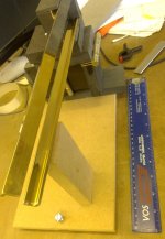
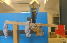
I attach a picture of my "rig" - this is not a real set up, i just put some old rails on it to show you. 6mm (M6) bolts have a 1mm pitch so glue the nut to the underside in a wee recess and you're there...........I like the idea of having a way of measuring the friction. That is really good and relatively easy solution.
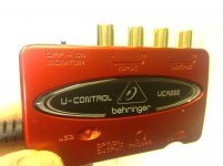
ADC, analogue to digital converter, i chose a behringer, pic attached at ~£20 over the focusrite that is probably better at £100. all the plots i post come through this, my only problem with it is that its grounding is not the same as my playback amp and you can see hum on the plots that i cannot hear in real life, but its so low level i have not worried to date.I’m unsure of the abbreviations that you use. ADC and VA. Would you mind enlightening?
VA is visual analyser and is a free download, just google it and you will find it
Post 4287 shows the set up with a pair of horizontal rails. i am now using one above the other but the concept is the same for the balls etc.Lastly and most importantly. I have searched just now and I remember doing this in January. I cannot find non recirculating 6mm ceramic balls on an aluminium v rail. Have you a supplier? And pictures of yours. I’m struggling with this bit quite a lot. Thanks
With your set up you only need one rail because the stylus is the stabiliser to tipping as you know.
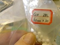
I got balls from amazon or ebay, it would be nice to find G5 closer tolerance balls, but G10 is what they normally send despite the advert .......you might experiment with diameter as you will have a different result in your configuration.
Aluminium anodise 1/2" angle at 1/8" for the rail and 1/16" for the cart is my recommendation, then you've only got to grind or cut the cart rail to fit.........!
Attachments
Two further points i might have noted,
Being (and remaining) truly level is absolutely important, flexible plinth mountings are not good for this. if the cart is low friction and free to run (lock it off with zero vtf if you can) it will best demonstrate level.
If you are to experiment with rails, balls and materials you might do this as an experiment on the sine bar rig without building a complete set up, optimise it first and then build it in
mike
Niffy, thank you for the information. I need to go over this thread and have a look at your design. I remember seeing it ages ago. This thread is so huge. I’ve read it twice now up until page 290 odd but it keeps developing, I need to catch up. I think your method is clearly the one to go with given technical ability and knowledge but when you are limited in both it seems a bit daunting. I will have a good investigation though.
Mike, thanks for all your answers. This approach seems more manageable to me given skills, tools etc. And clearly has excellent results. In an ideal world it would be good to go through all approaches... and I may do that in time.
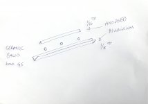
I have had a bit if read going backwards to get an idea of development. I need to read more but I think I now understand. On the one rail vertical movement is fine as the rail pivots around the ball..correct?
I have posted a drawing to confirm that my understanding is correct.
Mike, thanks for all your answers. This approach seems more manageable to me given skills, tools etc. And clearly has excellent results. In an ideal world it would be good to go through all approaches... and I may do that in time.
I have had a bit if read going backwards to get an idea of development. I need to read more but I think I now understand. On the one rail vertical movement is fine as the rail pivots around the ball..correct?
I have posted a drawing to confirm that my understanding is correct.
Attachments
I agree, its huge but so well worth a read to benefit from what these great folk have already done!!Niffy, thank you for the information. I need to go over this thread and have a look at your design. I remember seeing it ages ago. This thread is so huge. I’ve read it twice now up until page 290 odd but it keeps developing, I need to catch up.
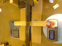
I think you only need two balls, in fact three in line guarantee a variation in contact as there will be tolerances. The ball movement needs to be restricted, here is a pic of an old rail to show what i do.I have had a bit if read going backwards to get an idea of development. I need to read more but I think I now understand. On the one rail vertical movement is fine as the rail pivots around the ball..correct?
I have posted a drawing to confirm that my understanding is correct.
Concerning the vertical pivot, i feel you will either get a small slide to achieve that, same as the current bearing, or perhaps a combination movement, either way no worse than current i feel.
I will get out some old bits and glue up a mock up later if you tell me the length of your arm wand.
Mike
You are absolutely right, I will read🙂.
I don’t know how to use the quotes as you do. But anyhow, did you mean to post a picture? Showing me what to do? With the restriction of ball movement.
That’s really kind of you. The total length of the wand is 200mm. The pivot to stylus is 75mm and the stylus to carriage is 85mm. ..Give or take, measuring with a tape measure.
I’m sure as I start to play around with it it will all make sense as these things tend to do. I particularly like the idea of the test rig. At the moment I’m just watching the bearings to see how much drag there is. All very approximate although one can tell what works and what doesn’t. It’s good to have something more concrete.
Someone on here taught me! - so at the bottom of the post you wish to reply to is a set of quote marks, click on this and click on reply and you will get a copy of all the original betweenYou are absolutely right, I will read🙂.
I don’t know how to use the quotes as you do.
- then edit between those as you wish, if you want a series like i do copy the entire quote first and paste it in several times and edit as you go down the answers
I took the pic, just forgot to attach it! - i will try again now.But anyhow, did you mean to post a picture? Showing me what to do? With the restriction of ball movement.
I will have a go at a lash up and see!You are absolutely right, I will read🙂.
That’s really kind of you. The total length of the wand is 200mm. The pivot to stylus is 75mm and the stylus to carriage is 85mm. ..Give or take, measuring with a tape measure.
Attachments
This isn't all about friction. Newtons first law of motion is at play here. An object at rest wants to stay at rest. even a frictionless bearing would show cantilever deflection with eccentricity unless there is no mass in the horizontal plane. This is a classic pendulum equation with the cantilever being the lever, the stylus being the fixed point and the carriage being a rather large mass at the end of the pendulum.
Mass or no mass
Which argues for minimum mass, but experience of others lead to higher mass??......i expect i have it wrong! - for me, all learning and input most useful, mike
This isn't all about friction. Newtons first law of motion is at play here. An object at rest wants to stay at rest. even a frictionless bearing would show cantilever deflection with eccentricity unless there is no mass in the horizontal plane. This is a classic pendulum equation with the cantilever being the lever, the stylus being the fixed point and the carriage being a rather large mass at the end of the pendulum.
Which argues for minimum mass, but experience of others lead to higher mass??......i expect i have it wrong! - for me, all learning and input most useful, mike
Soundblaster. I’m really comforted by your, niffy and mike’s input. I was unsure how much was acceptable in terms of lateral flex. The air bearing has pretty much none and I don’t have access to a pivoted arm to compare. It seems that currently mine is within acceptable tolerance, it sounds fine and the stylus seems to be moving in a satisfactory fashion. So I am happy. The tonearm works ok. However it’s fun to keep digging and try to improve.
I have a few things to try with the bearings and then I’ll try mikes approach I think. And if I’m feeling, brave and rich I might have a look at niffy’s one day ...that might be beyond me.
I have a few things to try with the bearings and then I’ll try mikes approach I think. And if I’m feeling, brave and rich I might have a look at niffy’s one day ...that might be beyond me.
I will have a go at a lash up and see!
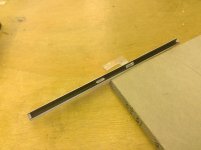
Here is my latest tonearm, called "the oak" for obvious reasons.
Offcuts from a cupboard project!
I just took my recently redundant brass rails, they are not as good as anodised, you won't want the top one in your configuration if you go this route.
Then i took an old carriage rail which is certainly not pristine.
As this is classic V on V the carriage travel is twice the ball travel.
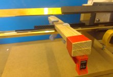
I set it up on the sine bar, neutral VTF, i.e. zero and the blu tack gets the centre of gravity below the pivot balls so that it returns to centre when it pivots in the vertical plane. This is only necessary for the experiment to work not on an arm in use.
Apologies to Ortofon for taping their cartridge to it but one channel went down....
I felt this pivoted better with 5mm balls than 6mm, which is logical as the scrub radius would be less. possibly even smaller would be better but getting the right clearances becomes tricky.
So each ball has 4 points of contact, two top and two bottom and in the radial motion it runs similar to my tonearm, it needs around 1mm in 300 to continue to run when started and slightly more to start from rest.
I have never gone down the jewel route, so i don't know how much better that might be but i am fairly sure this will better the BB's in motion and likely be similar to them in vertical pivot.........
I then set vtf at 1.75 with another lump of blutack and this is consistent to '00ths, i.e. stays in the 1.7's over a 3mm height difference which is the accepted maximum warp and returns to stable immediately, so i reckon this could work for you, no guarantees but a good value experiment and no chattering BB's around!
Mike
Attachments
Hi SB,
I'll use my arm and cartridge as an example.
My carriage Inc' cartridge weights 55g. My cartridge has a compliance of 22um/mN (high compliance). Normal wisdom would say that the ideal effective mass would be around 12g for this cartridge, and with my arm it is in the vertical plane. You want the resonant frequency of the cartridge suspension/mass to be about 10hz so that it is about an octave below the bottom of the audio band (20hz) and an octave above the highest frequency at which significant warps occur (5hz). This is only true in the vertical plane. Laterally there are no warps only eccentricity and this occurs at 0.55hz. Laterally you can tune the resonance to a much lower frequency before it is will be excited. With the mass of my arm this frequency is about 4.5hz. With a severely eccentric record where the groove moves back and forth by 1mm the cantilever will be deflected by a maximum about 0.08° due to the inertia of the carriage, below audibility. This is admittedly larger than with a 12g arm where the deflection would be only 0.018°. At 0.08° it is still below what is experienced by a 12g arm in the vertical plane due to warps on a typical record, about 0.1°. No one worries about excess deflection in the vertical plane.
The real advantage of higher lateral effective mass is found in the audio band especially in the bass. With my arm the cartridge body is held much solidly, moving much less than for a 12g arm, 1/4.5 times less ie over 12dB less. At 20hz with a 12g arm the movement of the cartridge body is only 10dB down compared to the motion of the stylus. At 55g it is 23dB down. Even if your speakers can't play as low as 20hz you still don't want your cartridge wobbling all over the place at this frequency.
It is assumed by many that it is important to have the vertical and lateral effective masses the same. There is no reason to make this assumption. The compliance of your cartridge is different in the two planes. Laterally the groove is modulated from 20-30hz. Vertically it is modulated from about 120hz. As modulation and compliance are different in the different planes the ideal mass is different too. The difference will remain at 12dB as frequency increases. The amount of cartridge body movement will decrease at 12dB/octave for both cases. By the time you get to 120hz, where stereo information begins, the amount of cartridge body movement, in both planes, is very small in absolute terms. (around 50dB down even with the 12g arm). The cartridge see the same relative movement of the stylus in both planes so the higher mass has no effect on stereo imaging.
The "tail wagging the dog" problem that is often leveled at linear arms is a myth. The benefits of a higher lateral mass massively outweigh any possible negatives.
Niffy
Here is my latest tonearm, called "the oak" for obvious reasons.
Offcuts from a cupboard project!
I just took my recently redundant brass rails, they are not as good as anodised, you won't want the top one in your configuration if you go this route.
Then i took an old carriage rail which is certainly not pristine.
As this is classic V on V the carriage travel is twice the ball travel.
I set it up on the sine bar, neutral VTF, i.e. zero and the blu tack gets the centre of gravity below the pivot balls so that it returns to centre when it pivots in the vertical plane. This is only necessary for the experiment to work not on an arm in use.
Apologies to Ortofon for taping their cartridge to it but one channel went down....
I felt this pivoted better with 5mm balls than 6mm, which is logical as the scrub radius would be less. possibly even smaller would be better but getting the right clearances becomes tricky.
So each ball has 4 points of contact, two top and two bottom and in the radial motion it runs similar to my tonearm, it needs around 1mm in 300 to continue to run when started and slightly more to start from rest.
I have never gone down the jewel route, so i don't know how much better that might be but i am fairly sure this will better the BB's in motion and likely be similar to them in vertical pivot.........
I then set vtf at 1.75 with another lump of blutack and this is consistent to '00ths, i.e. stays in the 1.7's over a 3mm height difference which is the accepted maximum warp and returns to stable immediately, so i reckon this could work for you, no guarantees but a good value experiment and no chattering BB's around!
Mike
Thanks Mike. That helps a lot to see what’s going on there.
I need to go back and see how your arm has developed. I’m unsure of the use of the top v amongst other things. How have you connected the arm to the top of the v? It’s unclear from the pictures. Is it carbon fibre bonded onto the top of the v?
Mike. Maximum mass makes sense. When the disc was cut, the lateral motion was tied to a slowly advancing lead screw that had NO compliance.. Ideally, we would all have tonearms that had a leadscrew that advanced the stylus across the record at the exact same rate the groove was put down. For any given moment, you want zero lateral and vertical movement of the cartridge. Including those freedoms of movement are a compromise to the real world issues of vinyl. Warps and eccentricity. If there were no warps, the tonearm need not move vertically other than to place it on the record. Horizontal movement is necessary to move the stylus across the record. High mass in the horizontal plane moves the resonant frequency created by the lateral flexibility of the cantilever way below reproduction range.. Eccentricity of a 33.33 rpm record should be ~0.55Hz. Resonant action will tend to create harmonics above this frequency.. moving the resonance as low as possible also keeps the harmonics very low.. I would like to add that if you're trying to track a record that has more eccentricity than the cartridge/cantilever can handle, you should probably get another copy of said record.
Last edited:
Mike. Maximum mass makes sense........ .
Hi SB,
I'll use my arm and cartridge as an example.....................
The "tail wagging the dog" problem that is often leveled at linear arms is a myth. The benefits of a higher lateral mass massively outweigh any possible negatives.
Niffy
Its great to have input from you gents and others who actually understand the scientific background, i try to, but rely on hands on experiments to prove (or often disprove!) my best guess. This morning i moved Vertical centre of gravity around on my cart and separately on my paralelogram having concluded this would make all the difference. Alas i cannot say i produced any repeatable improvement in results at all in measures, tracking or sound! - this is not because things are already perfect either, its just that neither of these are the next critical improvement clearly!
just going back to mass, i will soon build a neat version of the current set up which will remove mass, so i will be able to start low and experiment with increasing horizontal mass.
M
Thanks Mike. That helps a lot to see what’s going on there.
I need to go back and see how your arm has developed. I’m unsure of the use of the top v amongst other things. How have you connected the arm to the top of the v? It’s unclear from the pictures. Is it carbon fibre bonded onto the top of the v?
Yes JW thats a carbon strip bonded on there so its really stiff and light.
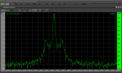
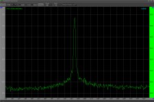
Early on i did a series of measures that demonstrated the benefits of stiffness in reducing resonances and the sidebands that one sees as a result on a 1khz test tone, here attached for interest a start plot and current, this is what you will easily be able to do with VA..........!! note the scale changes as i got more refined in its use.
I need the top V because my arm does not pivot in the vertical plane like yours, i have the paralelogram motion that keeps the cartridge at constant orientation in the horizontal plane as it moves vertically, others don't do that and achieve great results, but i like the idea, however it means i need a secondary rail to stop the whole thing swaying about and i started with two rails one behind the other and moved on to the V over the V that you now see.
Attachments
Yes JW thats a carbon strip bonded on there so its really stiff and light.
Early on i did a series of measures that demonstrated the benefits of stiffness in reducing resonances and the sidebands that one sees as a result on a 1khz test tone, here attached for interest a start plot and current, this is what you will easily be able to do with VA..........!! note the scale changes as i got more refined in its use.
I need the top V because my arm does not pivot in the vertical plane like yours, i have the paralelogram motion that keeps the cartridge at constant orientation in the horizontal plane as it moves vertically, others don't do that and achieve great results, but i like the idea, however it means i need a secondary rail to stop the whole thing swaying about and i started with two rails one behind the other and moved on to the V over the V that you now see.
Thanks Mike. I’ll do some reading and buy some bits... I’m not the fastest worker so don’t hold you’re breath. 😀
Appreciate all the input chaps.
Thanks Mike. I’ll do some reading and buy some bits... I’m not the fastest worker so don’t hold you’re breath. 😀
Appreciate all the input chaps.
Don't forget to post photos and details of your deck JW, folk here will appreciate that as well!
Mike
BTW, if the wand was under the rail the neutral balance bit would be easier....
- Home
- Source & Line
- Analogue Source
- DIY linear tonearm