The build has started.
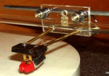
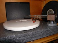
I had to make a few adjustments in that finding a 5mm brass tube for the bearings nearly impossible where I live. So I switched from metric to standard and used a 3/16 x 5/16 x 1/8 inch bearings. This allowed me to use the CF tubes as a bushing for the bearings. A few fit and finish adjustments and this part of the arm will be done. Just have to make the base to complete it. Will use my Denon 103R as the stylus before I put on my Lyra.
I had to make a few adjustments in that finding a 5mm brass tube for the bearings nearly impossible where I live. So I switched from metric to standard and used a 3/16 x 5/16 x 1/8 inch bearings. This allowed me to use the CF tubes as a bushing for the bearings. A few fit and finish adjustments and this part of the arm will be done. Just have to make the base to complete it. Will use my Denon 103R as the stylus before I put on my Lyra.
Attachments
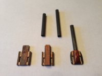
I had to make a few adjustments in that finding a 5mm brass tube for the bearings nearly impossible where I live. So I switched from metric to standard and used a 3/16 x 5/16 x 1/8 inch bearings. This allowed me to use the CF tubes as a bushing for the bearings. A few fit and finish adjustments and this part of the arm will be done. Just have to make the base to complete it. Will use my Denon 103R as the stylus before I put on my Lyra.
Nice work great visual. Have you considered filling the tube with fine sand or better yet glass sandblasting beads? Best regards Moray James.
Colin, have you tried different arm wand materials to determine if there are significant differences? I am specifically curious about using Easton aluminum arrow shafts that have been mentioned prominently in the Nanook and Schroeder arm threads. I suspect there will be little difference among materials due to the shortness of the arm but I think it will be worth looking into.
One more question. Have you used a measured the amount of clearance between the ID of the bearings and the OD of the brass? I have a small Taig modelling lathe on which I will turn some parts and I'd like to get a feel for how tight the tolerances you have used.
One more question. Have you used a measured the amount of clearance between the ID of the bearings and the OD of the brass? I have a small Taig modelling lathe on which I will turn some parts and I'd like to get a feel for how tight the tolerances you have used.
what is your conrern?
the weight of the tube factors into nothing. The more energy you can absorb from the system the better.Best regards Moray James.
Was thinking about a little A grade balsa wood. Wouldn't need to stuff it the complete length either to cancel any resonance. I want to keep the weight really low.
the weight of the tube factors into nothing. The more energy you can absorb from the system the better.Best regards Moray James.
hard to tell
both physical material changes including moving mass and geometrical changes were made to the design. COG changes are likely the major factors here but there is no way to really tell when changing two things at a time. Changes in the COG will impact both the dynamic balance and performance of the arm. Best regards Moray James.
Colin, have you tried different arm wand materials to determine if there are significant differences? I am specifically curious about using Easton aluminum arrow shafts that have been mentioned prominently in the Nanook and Schroeder arm threads. I suspect there will be little difference among materials due to the shortness of the arm but I think it will be worth looking into.
One more question. Have you used a measured the amount of clearance between the ID of the bearings and the OD of the brass? I have a small Taig modelling lathe on which I will turn some parts and I'd like to get a feel for how tight the tolerances you have used.
both physical material changes including moving mass and geometrical changes were made to the design. COG changes are likely the major factors here but there is no way to really tell when changing two things at a time. Changes in the COG will impact both the dynamic balance and performance of the arm. Best regards Moray James.
Morey James, when you talk about the tube were you referring to the boro glass tube that the arm rides on? If so yes, that will be filled with wooden dowel so that it can be held in compression to the support assembly.
If you were talking about the CF tone arm tube and CW tube then I thought weight was everything.
If you were talking about the CF tone arm tube and CW tube then I thought weight was everything.
yes the glass tube which the carriage rides upon
That is your best opportunity to damp system vibrations. The harder the tube material the better both from a friction point of view and from a damping point of view. Sorry I was not clear about. Balsa wood would be good damping in the arm and counterweight tube. Best regards Moray James.
Morey James, when you talk about the tube were you referring to the boro glass tube that the arm rides on? If so yes, that will be filled with wooden dowel so that it can be held in compression to the support assembly.
If you were talking about the CF tone arm tube and CW tube then I thought weight was everything.
That is your best opportunity to damp system vibrations. The harder the tube material the better both from a friction point of view and from a damping point of view. Sorry I was not clear about. Balsa wood would be good damping in the arm and counterweight tube. Best regards Moray James.
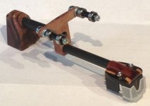
Arm wand materials tried were steel, glass and carbon fiber. I preferred carbon fiber due to its lack of sonic imprint and clean balance across the spectrum. I have damped the 10 mm tube with a rubber I ring at each end inside the tube. I feel the latest iteration of arm is an even better tracker and easier to set tracking force, this puts all the mass below the bearings which is good, due to the set screw to lock the arm it also facilitates the exchange of a new and or different arm tube.
Colin
Colin
Colin,
One more question. Have you used a measured the amount of clearance between the ID of the bearings and the OD of the brass? I have a small Taig modelling lathe on which I will turn some parts and I'd like to get a feel for how tight the tolerances you have used.
Hi LFM et al,
Change in plans I will be leaving on trip Friday not today (Thursday) so I have had time to do some listening. I won't get into details but I am pleased beyond words!
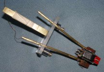
LFM, you ask about tolerances. I wanted the same information when we still didn't know whether the brass tube went between the bearings or into the bearings. I had a bearing with a 5mm bore so I turned a piece of stock to the exact dimension Colin spells out in his diagram. Couldn't just tell by looking at the drawing, my eyeball is calibrated in inches not metric. I couldn't believe how loose a fit that bearing was on the test rod. That clinched it, the bearing slides over the full length of the brass shim.
So for my carriage I dispensed with the brass tube altogether and turned a simple aluminum rod to a loose sliding fit and made sure it was smoothed with 1000 grit wet and dry paper. One end was left larger to press fit into the carrier piece and project about a mm to space the bearings out from the carrier. Small brass clock bushings were then used to set the maximum spacing of the bearings at 5mm. The bushings are just force fit to the right dimension at bearing assembly. As long as the bearings are free to be driven to their maximum spacing by the weight of the assembly and their motion on the glass rod you have achieved the purpose of the brass spacer. The bearing has to sit on something and should be free enough as to not bind.
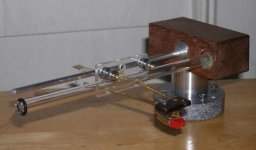
Finished off the new carriage with the parts of the glass V track Cantus style arm. The pictures will tell the rest of the story. I'm using an Empire 2000 E cartridge that I had written off in other arm tests as not being up to the sonic standards of my Ortofon OM cartridge. Like Colin says, it is amazing how this LT arm makes a $100 cart sound like one costing far more.
I'm also most pleased to see the active response from forum members actually building this version of the linear tracker. We never had this response on the CANTUS thread. GREAT!!!!
BillG
Attachments
Bill,
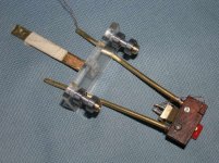
The bearings should be able to slide freely when not on the tube, the undersized brass bushing allows a very slight tilt to the bearing assembly to minimize contact area with the bras bushing so that when placed on the tube the bore rests on two edges rather than the full bore, his also reduces friction") . It works, I'm sure you can trust me by now, the glass tube is what makes this precision happen.
. It works, I'm sure you can trust me by now, the glass tube is what makes this precision happen.
Colin
The bearings should be able to slide freely when not on the tube, the undersized brass bushing allows a very slight tilt to the bearing assembly to minimize contact area with the bras bushing so that when placed on the tube the bore rests on two edges rather than the full bore, his also reduces friction
. It works, I'm sure you can trust me by now, the glass tube is what makes this precision happen.Colin
BillG, the inner race of the bearing ought not be free to rotate on a shaft...
Bear, that is what I think too. Conventional wisdom. Read Colin's posts carefully. He states that in his design you are not relying on the rotation of the bearing races only, you have a backup system in play. I'll find the post. He gives the diameter of the brass shim. It is a loose fit in the bearing bore. His pictures show the position of the bearings. In one pic the bearings are slid together, touching each other. In the other picture they are slid apart out where they belong with the specified 5mm between them. With sensitive, low friction bearings like these the weight of the carriage is going to keep the bore free of rotation on the shaft unless the inner race gets locked to the outer race. In previous use of these bearings I have observed that a tight fit on the shaft will distort the inner race enough to adversely affect the performance of the bearing. So one must be careful when fitting them to a shaft. I made my bearing a smooth sliding fit on the shaft.If there is any trouble I can lock the bearing to the shaft and see what is going on. So far all is well.
BillG
Last edited:
Bear, that is what I think too. Conventional wisdom. Read Colin's posts carefully. He states that in his design you are not relying on the rotation of the bearing races only, you have a backup system in play. I'll find the post. He gives the diameter of the brass shim. It is a loose fit in the bearing bore. His pictures show the position of the bearings. In one pic the bearings are slid together, touching each other. In the other picture they are slid apart out where they belong with the specified 5mm between them. With sensitive, low friction bearings like these the weight of the carriage is going to keep the bore free of rotation on the shaft unless the inner race gets locked to the outer race. In previous use of these bearings I have observed that a tight fit on the shaft will distort the inner race enough to adversely affect the performance of the bearing. So one must be careful when fitting them to a shaft. I made my bearing a smooth sliding fit on the shaft.If there is any trouble I can lock the bearing to the shaft and see what is going on. So far all is well.
BillG
While I was typing this, Colin wrote the previous (337) explaining why he does it this way.
Colin,
I understand clearly what you are saying. I do take exception to your claim that this reduces friction. Under operating conditions the only parts that are moving are the balls and the outer race. The weight of the assembly keeps the inner race from rotating on the undersize brass tube. No rotation - No friction to reduce. No way is it possible to affect the frictional forces inside the bearing or the friction in the steel to glass interface. Making the bearing be just free enough to prevent distorting it, as with these small parts, which could happen with an interference fit, is important and desirable, but not for the reasons you give. Also having the bearings free enough to slide outward to the limit stops under the weight of the assembly sets the alignment and permits free motion of the outer race along the surface of the glass tube.
Best regards and no offence. The performance of this arm speaks loudly.
BillG
Bill,
No offence taken, if anything it goes yet another step to show how well it works conceptually even without razor tolerances. One could look at it as a small form of decoupling, I'm just ecstatic to see this arm being built up and clearly working as trouble free as my two are!!.
Colin
No offence taken, if anything it goes yet another step to show how well it works conceptually even without razor tolerances
. One could look at it as a small form of decoupling, I'm just ecstatic to see this arm being built up and clearly working as trouble free as my two are!!.Colin
- Home
- Source & Line
- Analogue Source
- DIY linear tonearm