Mic capsules distorting at low level in binaural dummy head? Resistor help please?
Hi folks.
So I've built a binaural dummy-head mic featuring the Panasonic WM61a capsules. The problem is that the mic capsules seem to be distorting, apparently caused by upper-mid frequencies. Here's a very short demo showing what I mean.

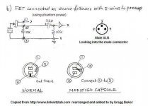
I performed the linkwitz mod on the capsules as the idea is to use the head at gigs, and built a pair of phantom-powered, phase inverting circuits, one for each mic. I used this circuit:

The only difference is that Terminal 3 on the capsule goes to ground as per the advice of Bill Wall.
However, as I said the capsules are distorting easily, at low input settings, with human voices seeming to break up very easily. Both are doing it the same way. So I was wondering if anyone might have any idea what might be going on here? I have another head with the same capsules, unmodified, and that can handle much higher levels than these, even though the Linkwitz mod is meant to raise the SPL.
If anyone's got ANY ideas I'll be incredibly grateful, I'm really not sure what to do here now.
Thanks
Nate
Hi folks.
So I've built a binaural dummy-head mic featuring the Panasonic WM61a capsules. The problem is that the mic capsules seem to be distorting, apparently caused by upper-mid frequencies. Here's a very short demo showing what I mean.
I performed the linkwitz mod on the capsules as the idea is to use the head at gigs, and built a pair of phantom-powered, phase inverting circuits, one for each mic. I used this circuit:
The only difference is that Terminal 3 on the capsule goes to ground as per the advice of Bill Wall.
However, as I said the capsules are distorting easily, at low input settings, with human voices seeming to break up very easily. Both are doing it the same way. So I was wondering if anyone might have any idea what might be going on here? I have another head with the same capsules, unmodified, and that can handle much higher levels than these, even though the Linkwitz mod is meant to raise the SPL.
If anyone's got ANY ideas I'll be incredibly grateful, I'm really not sure what to do here now.
Thanks
Nate
Last edited:
Nate... I'm not expert at all on mic techniques and circuitry but I would suggest at least checking that the capsule is operating with the correct voltage according to the data sheet. Perhaps the capules you are using don't behave as expected when modified away from their original design, that's something I have no experience of.
Also, I think this might get more exposure in the "analog source" section. If you want it moving just ask")
Edit... a scope check might reveal where the distortion originates. ie mic or following stage.
Also, I think this might get more exposure in the "analog source" section. If you want it moving just ask
Edit... a scope check might reveal where the distortion originates. ie mic or following stage.
Cheers Mooly, I wasn't sure where best to put this, if you wouldn't mind moving it to where you think it should be that'd be excellent.
The electronics aspect of this project was admittedly a little over my head, so Bill Wall really helped me through it a fair bit via email. He assured me the voltage output was correct, but perhaps that's at fault. I'll take a look with the multimeter and see what voltage is being put across the cap. Would it be across terminals 1 and 2 I'd want to test?
I'm not sure what a scope test is so I'll look into that!
So I put the multimeter to the thing and:
- With the mic connected, I put the probes across 2 and 3 and it reads 6v.
- I don't know if this is of note, and I'm probably betraying my lack of electronic knowledge, but with the microphone disconnected, it reads 46v across 2 and 3.
Scott, my understanding was that the Linkwitz mod makes 2 hot, so I thought I'd connected this properly. Bill's advice was to connect it in this way, I'll try reversing them and see what happens.
As I say, I bit off a little too much doing this project, I'm great with the building aspect, not so much with the electronics, so I kind of feel like I'm bumbling my way through this stage of it!!
Moved to Analogue Source
The 46 volts with the mic disconnected sounds OK as that will be the phantom PSU voltage. With the mic in circuit and drawing its rated current the voltage settles to around the 6v you measure. That to me sounds OK.
Scott is a real expert around here on these kind of FET related problems so well worth trying his suggestions.
Looks like in copying things often there was a switch. In drawing below I see your same images of the cut but if you look closely they went with a simple direct connection to an XLR. The numbers in the little circle are the capsule pins (1 is hot) and the 2 here refered to XLR pin 2.
Note: pin 3 must go to an AC ground. In the original pin 1 was connected to the battery so it did not matter but you must ground pin 3.
Note: pin 3 must go to an AC ground. In the original pin 1 was connected to the battery so it did not matter but you must ground pin 3.
Attachments
Last edited:
Hmm I swapped the connections around on one of the capsules and it seems to have sorted it.. going to solder it up properly this morning and see how it goes. Looking at all the wiring diagrams for the mod I can see what you mean, it does look like I did it back to front!
Is there any chance I'll have damaged the capsule by having it wired back to front?
Is there any chance I'll have damaged the capsule by having it wired back to front?
That seems to have done the trick. I've shouted as loud as I dare, and turned my monitors as loud as they physically go, and can't get it to distort. I'm heading into Trafalgar Square on Saturday, so I'll set it up in the middle of the crowd and do some recording with the H4N.
But I don't think it's premature to say thankyou guys, particuarly Scott obviously. I don't think I'd have found that fault, and may well have ended up rebuilding the entire circuit incorrectly again to try and solve it. So thanks very much.
I'll report back in a few days with some recordings.
But I don't think it's premature to say thankyou guys, particuarly Scott obviously. I don't think I'd have found that fault, and may well have ended up rebuilding the entire circuit incorrectly again to try and solve it. So thanks very much.
I'll report back in a few days with some recordings.
Aye, I've got a nice pair of Roland CS10EM ear mounted mics, they do a lovely job. The head has the advantage of incorporating replica ear canals for vertical localisation, as well as obvious being a free-standing mic.
This recording was done with the Rolands mounted inside a dummy-head:
Binaural Birds by Nathan Gallardo on SoundCloud - Create, record and share your sounds for free
I'll definitely be back with some more in the next few days
This recording was done with the Rolands mounted inside a dummy-head:
Binaural Birds by Nathan Gallardo on SoundCloud - Create, record and share your sounds for free
I'll definitely be back with some more in the next few days
Hmm I swapped the connections around on one of the capsules and it seems to have sorted it.. going to solder it up properly this morning and see how it goes. Looking at all the wiring diagrams for the mod I can see what you mean, it does look like I did it back to front!
Is there any chance I'll have damaged the capsule by having it wired back to front?
Very unlikely.
So that has definitely made an enormous difference. It no longer breaks up at speaking levels as it was before. So thanks Scott for helping me fix the capsule issue. However, it seems there was another issue involved which has only now become apparent.
I've been testing it with two devices: a Zoom H4 and into my Focusrite Saffire 6.
I don't think the Zoom is any good for the head. Shouting at the head creates distortion on the Zoom recordings, but I believe that's the Zoom as opposed to the capsules. It only has 3 input settings, low-medium-high, and an in-menu input level which is digital and hence useless. I understand my circuit outputs a line level signal (I'm looking to you for confirmation here....) and the Zoom inputs are mic level, so while it'll be fine for recording ambience and whatnot but it'll be no good in a gig setting. It even distorted recording a noisy corridor at uni today. Any fix for this?
Into my Saffire 6 is much better, but still seems problematic. With gain set to zero and the pad initiated it still seems to distort a little if I shout into the mic. It's not peaking in Logic or on the interface, so I presume it's happening at the capsule. That said, I'm not sure if the mic should be able to handle that kind of level? Is it realistic to expect it not to break up if I shout directly into it? I did a short recording so you can hear the breakup:
ClapsTesting01 by Nathan Gallardo on SoundCloud - Create, record and share your sounds for free
Those are the hardest claps I can muster at the beginning, followed by my shouting into the ears. This isn't very scientific I know...
Any thoughts?
Quite frankly, I cannot hear the overload.....????
Build yourself a decent preamp with padded variable output. TL072s, 5534,5532 or even some of the SSM chips should do the trick of optimizing input volume.
This might also give you some ideas
D.I.Y. Recording Equipment | DIY Microphones, Preamps, Compressors, etc.
Build yourself a decent preamp with padded variable output. TL072s, 5534,5532 or even some of the SSM chips should do the trick of optimizing input volume.
This might also give you some ideas
D.I.Y. Recording Equipment | DIY Microphones, Preamps, Compressors, etc.
Sorry to bump this but I'm still having some troubles :/
I tested the mics in front of a PA the other day and they held out well, but they still broke up at high volume, and I'm certain we didn't reach the 130db limit these capsules are meant to be able to handle post-Linkwitz.
I've measured the voltage across the capsule while powered, ie. between terminals 1 and 2, and it reads consistently at around 14v. This definitely seems wrong, though I worry I am taking the measurement incorrectly.
If that is the correct way to measure the voltage, what would that reading indicate? That the capsules are receiving too much power? What could be the cause for that in the circuit?
I'm sorry for all the novice questions, I really appreciate your efforts to help me though!
The voltage across the capsule must be within the recommended limits for the particular device.
Refering to your original diagram in post #1 the voltage across the capsule is determined by the 33K and the two 5K6 resistors. If you have used a different capsule to the one the circuit was designed for then the voltages will be different as the capsule will probably have a different current draw.
Altering the 33K will alter the voltage across the capsule. Higher t'ohmage and the lower the volts on the capsule.
Refering to your original diagram in post #1 the voltage across the capsule is determined by the 33K and the two 5K6 resistors. If you have used a different capsule to the one the circuit was designed for then the voltages will be different as the capsule will probably have a different current draw.
Altering the 33K will alter the voltage across the capsule. Higher t'ohmage
and the lower the volts on the capsule.- Status
- This old topic is closed. If you want to reopen this topic, contact a moderator using the "Report Post" button.
- Home
- Source & Line
- Analogue Source
- Mic capsules distorting at low level in binaural dummy head. Why :(