Dear Doug, I've tried, and found it really interesting.
My system is the opposite of what people expect from tubes: the sound is cold and sharp, and bad recordings become unlistenable. I do not know if this is due design, or to the very few components, no output or crossover caps (and very few along the path - no electrolytics at all) or simply from the fostex 208 blh. Of course well-known faults are there, but being a chamber music addicted I'm happy that way.
My naive idea is that the arm (and TT too) should not play at all (that's the role of the cartridge, and everyone buys what he likes). Listening to a new arm, when hearing a different sound from my references I think there's something wrong.
The Rabbit-arm sounds very good, very detailed, but sounds very different. So the question is: is this arm wrong, or the normal ones? Because cartridges have been designed for 60 years for arms with 22°- 24° offset (and tracking error + - 1 °).
When I get interested in this thread I wondered: facing a curve, is better to steer the wheels or rub against the guard rail? 22° are certainly too much, but 0° is correct? After all I read and tried, I've not yet found the answer.
Carlo
Construction: the belt is the type used for walkman, tape deck etc - Pulleys were turned, but it is not difficult to find 20 and 30 mm ones (cnc parts), just the ratio counts. Someone that likes precision can try to use timing belt and pulleys, but I suspect that friction increases, and decreases the elasticity: imho elasticity is positive, if not essential.
Attachments
There is a circle on a 0.7071 Birch, that will give you tangency through the complete 30° translation.
With standard pulleys as Carlo's design there are 3 nulls 0°, 15° and 30°.
Between 0° and 15° the biggest error is 0.3° and 0.22° between 15° and 30°
BUT in the same geometry it's possible to get tangency with small modifications to the pulleys.
Found this when trying to confirm geometric calculations algebraically.
Hi Carlo,
I've had an idea that may help reduce lateral tracking error even further in the rabbit. Hopefully I understand your design. Please correct me if I make any errors in my assumptions. Ideally one of the pulleys should be elliptical in order to achieve zero tracking error across the whole record. Machining an elliptical pulley is no trivial task. A piece of relatively thin walled tube can be gently squeezed in the softly padded jaws of a vice to deform it. As long as the deformation is small and the ratio of the required ellipse is not too large the resultant ring will be roughly elliptical. Even though the result will not be absolutely perfect it will be pretty close. It would probably result in lower error than a perfectly circular pulley.
Niffy
Last edited:
Niffy - Machining an elliptical pulley is no trivial task
Exact, quite impossible: and already discussed with Doug. A simple solution found was a bit of eccentricity of the pivot with respect to the movable pulley - # 1620 -.
Then the meticolous work of 2wice and the precision reached had made that kind of complications completely useless: I dare anyone to set up a cartridge (more, his cantilever - not always so precisely aligned) with an accuracy of far less than 1 °, especially now that some beautiful mind likes to make them roundish.
Congratulations 2wice: a really interesting geometry, and new, I think.
I tried to understand how is designed: at first sight it resembles that of your #1400 (without the "tail") but is instead completely different. There is no longer a real Thales circle: no arm point - even virtual - seems to follow any. So it's not even a Birch variant. The only thing that comes to mind is the geometry of the LT, but with the drawings found I wasn't able to analyze it correctly - #1390
(attachment) a small idea for your wheeled transmission: the ratio is correct also with small pulleys, and with great precision (better than the belt)
carlo
Attachments
Niffy -
I dare anyone to set up a cartridge (more, his cantilever - not always so precisely aligned) with an accuracy of far less than 1 °, especially now that some beautiful mind likes to make them roundish.
carlo
You are completely correct. I normally say 0.5° so that I don't bruise anyone's ego. People do like to think they can align to arcsecond accuracy. I threw in a possible way of reducing error as this thread is about reducing lateral tracking error. So often in this thread accuracies are quoted to 3 or 4 decimal places.
Niffy
Hi Carlo
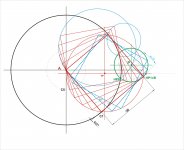
There is still a circumscribed triangle as in Birch, but now it falls on a circle that circumscribes a 150mm square = to tonearm length.
An elliptical pulley or deforming mechanism is no longer necessary, the eclipse is still there, just not very obvious.
I have calculated 0° pulleys for you on this geometry.
This would not have been found if I did not see your mechanism. Thanks.
Re: post 1686 with Carlo/Niffy quotes:
A delayed Happy New Year to all!
I would hope that no one is put off by the push for extreme accuracy. This thread has attracted some extremely clever contributions, not all of which require the same precision in reality. Thanks for saying so clearly, Niffy and Carlo!
Note: It has taken Direct Driver a lot of time and effort to get everyone to play on the same ANALOG page, and he should be thanked for staying with it.
Andy
Ray: Thanks for the confirmation. Does the longitudinal alignment of the stylus cantilever along the arm to point B change the equation?
Carlo isn't the only magician. 2wice has conjured more astonishing geometry. The acute angle between the crank and the wand in the first drawing might be a little difficult to deal with, though, if stylus drag isn't sufficient, but it might be that Carlo's belt or your idler idea could handle it. My arms all want the starting crank/wand angle to be >90 degrees.
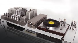
Carlo: If you align the Bunny crank at 90 degrees to the wand like in the the photo at #1682, will the arm move forward if you put side force on the headshell or do you have to pull it forward - for instance to move the stylus to a record? Speaking of #1682, that's a shelf full of very handsome equipment.
awolff761: Andy, re DD you're absolutely right. Thanks DD.
Carlo isn't the only magician. 2wice has conjured more astonishing geometry. The acute angle between the crank and the wand in the first drawing might be a little difficult to deal with, though, if stylus drag isn't sufficient, but it might be that Carlo's belt or your idler idea could handle it. My arms all want the starting crank/wand angle to be >90 degrees.
Carlo: If you align the Bunny crank at 90 degrees to the wand like in the the photo at #1682, will the arm move forward if you put side force on the headshell or do you have to pull it forward - for instance to move the stylus to a record? Speaking of #1682, that's a shelf full of very handsome equipment.
awolff761: Andy, re DD you're absolutely right. Thanks DD.
Last edited:
Will a laser cut acrylic pulley work ?
Regards.
Yes, I might be going this route. as it's fairly cheap.
A local company can only guarantee 250um accuracy so I'm looking for better.
Or my option is to go 250um bigger, stick it in the drill and sand it down to final size.
Niffy - Machining an elliptical pulley is no trivial task
a small idea for your wheeled transmission: the ratio is correct also with small pulleys, and with great precision (better than the belt)
carlo
Very nice and thanks Carlo.
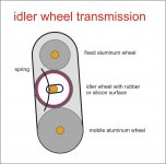
I'm trying another idea for the idler where it eliminates slip and is captured by the driving pulleys, I'll post once it is working in simulation.
2wice - I tried to understand graphically this new beautiful geometry. Perfect behavior, and strange at the same time: Hp1 seems to be the B point of the Birch - Thales, and seems to act like a breaking point of the geometry (see the blue squares). I had observed something like this analizing the arm with two cranks of Doug
Niffy, Andy - I would not be misunderstood.
theoreticians, physicists, scientists work with the precision necessary for their research, mathematically managing even errors deriving from observations (even 15 - 20 decimals, today): this allows experimenters, designers and even ignorant diyers like me to know how to build.
Doug - bunny: you're right, it would not move at all, in fact the initial angle is 120 ° - but the photo (sorry for that) is made during switching between different arms (there are not even cables connected) - now I'm waiting for a friend to lend me once again his SME and Rega, which I consider as references (I am not the only one)
carlo
Attachments
Dear 2wice,
looking at the problem posed by Doug (angle shaft crank near 90 °) I've seen a problem.
The rabbit belt gadget was found observing that - more or less - there was a linear relationship between crank and shaft rotation, with a ratio of about 2/3.
In this new geometry the relationship seems much more complex. How can be managed with pulleys?
Please see angles in attachment - it's just a graphic analisys, hope I'm wrong.
carlo
Attachments
No you are not wrong.
In my geometric analysis I did not see the slippage as it was so small.
I was using geometric constructs to look for shifts.
The calculations for the 2 pulley belted at this location goes as follows.
It's very much exploratory for me and my 3 pulley solution is using variable speed pulleys to get to 0°, just for sh!ts&giggles. I'm just having fun with it.
Each of the pics below shows variable degrees of change (delta) between the 2 pulleys, you picked this up.
Derive the delta in each 1/4 of travel for both pulleys and calculate the ratio for each 1/4.
The mean of those ratios is the pulley ratio to use for 2 pulley belted solution. 1:2.416
Plot the new position of the mean ratio pulley and derive the delta from the ideal variable positions.
Derive the new tangency errors from the new plots.
I think this is right.
Nah, scrap that, maths doesn't check out.No you are not wrong.
In my geometric analysis I did not see the slippage as it was so small.
I was using geometric constructs to look for shifts.
The calculations for the 2 pulley belted at this location goes as follows.
It's very much exploratory for me and my 3 pulley solution is using variable speed pulleys to get to 0°, just for sh!ts&giggles. I'm just having fun with it.
Each of the pics below shows variable degrees of change (delta) between the 2 pulleys, you picked this up.
Derive the delta in each 1/4 of travel for both pulleys and calculate the ratio for each 1/4.
The mean of those ratios is the pulley ratio to use for 2 pulley belted solution. 1:2.416
Plot the new position of the mean ratio pulley and derive the delta from the ideal variable positions.
Derive the new tangency errors from the new plots.
I think this is right.
View attachment 658262 View attachment 658263
Hi 2wice, my computer did not tell me of your new posts, sorry for the delay.
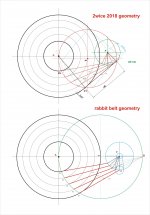
I had noticed on your graph that while the angles of rotation of the shaft are obviously constant (7.5 ° ca every step) those of the crank change progressively (reducing from 22° to 13 ° ca) and therefore also the ratio, that goes from 1:2.9 to 1: 1.7). So I wondered how pulleys could be used. Using a cam as idler wheel? But how? That geometry is so nice that a guiding gear must be found.
About my Birch arm, before building a better made version, i'm still struggling with the vectors breakdown, with results that do not convince me, even if they seem to explain some measures. The feeling I got from that analysis is that your transmission with the idler wheel would apply the forces on the pivots much better than the belt. i'll make a test, sooner or later
carlo
Hi Carlo
I have found the principal idea of the "gear", but the math is turning out tricky. It's a variable pitch pulley where the fixed and idler have the same perimeter and the the moving pulley shares the same geometry but the perimeter is in ratio to the fixed & idler pulleys.
This changes the radial acceleration of the moving pulley keeping it on the tangential line.
Hello,
I've read this thread and have been following it for quite a while. It's been fascinating seeing these latest developments with Carlo's Rabbit/Bunny type design, Twice's work. et all.
Before delving too deeply into it, I'm likely naively intrigued with the idea of using light weight gears ( likely spur ) in some configuration moving epicyclic rather than using pulleys based on Carlo's design. Very briefly looking at some tooth profiles , there is a claim that if well designed/made they roll rather than slide in regards to their contact friction point ( more research would be required ). They likely wouldn't be bearing any vertical weight, and would be mainly acting as a guide. they could be full size, or perhaps scaled up or down . They would have to be replaceable, and robust enough to rotate the crank, and survive negligent mishandling. I don't know if two gears and an idler gear - one gear fixed - as per Carlo's, an offset idler in the middle and an outside gear with the arm mounted would work somehow. There are further options with gears on the same axle, etc. perhaps to try to make the geometry work. Also, perhaps gears in combination with something else. This would likely require the lightest weight components, and the geometry utilizing the longest arm would help for leverage. The motion would be Epicyclic - two planets interlocked moving around and interlocked with a fixed Sun. The tonearm fixed rigidly on the outer planet axle.
Advantage ? : The biggest advantage to this and the reason I'm mentally pursuing it, is that I believe ( mistakenly? ) there may be zero skating utilizing toothed gears and an offset idler ( or more than just 2 gears ) with components mounted at an appropriate angle to the tonearm pulling direction. I'm hoping the arm will/can be mechanically locked if the arm is pulled in the tangential direction ( or any straight direction ), yet will be free to rotate. Personally, this idea is what I'm most interested in; in this thread - linear or close enough to linear but with no skating (or virtually no skating). The math/geometry/ratios would have to be worked out.
Backlash : As there is a constant load from the rotation of the record pulling the tonearm , I'm hoping the play/backlash will almost always be taken away by the record rotation pull holding the gear teeth in contact to one side, even when a gentle out of round event is occurring ? . Other events may upset the mechanism briefly, but I'm thinking it will return to the no backlash state quickly while the tonearm is constantly working it's way inwards. If not the case, I would further look into backlash reduction methods.
Friction : Perhaps the reason this whole idea is a waste of time - it may have too much friction to work at all. If the notion that the teeth roll on each other rather than slide is true - I'd be hoping the two interlocking contacts could sort of be counted as 2 bearings ( 2 poor bearings ? ). So it looks like there would be a total of 5 bearings ( possibly or likely too many ). I remember seeing a section on Yosh's site discussing some sort of idea that absolute minimal friction in the horizontal bearings wasn't necessarily desirable, but I don't remember the context.
An advanced refinement would be to add mechanical lifter to one of the gears (idler), to engage and disengage the gear in the gear-train when the arm is outside of the record area, so the arm can move freely with out having the gear-train engaged . This device could be mounted to the main fixed gear post.
If not the above due to too much friction - I'm curious also if there were additional pulleys added in some manner to a pulley arrangement , where upon the pulleys could rotate using the tonearm leverage, but the belts would be free to move but belt tensions would be just above the stylus drag - to somehow lock the arm like the gears above .
Sorry in advance from a less advanced contributor; as I realize this is not likely contributing to the job at hand, and likely will/may quickly be shown to be nonsense immediately. Too much thinking and not enough doing.
Thanks for sharing all your efforts,
Phil
ps. For anyone at a basic level without a lathe and other appropriate tools, the children's toy Lego has a product line called Lego Technic that has gears and pulleys ( and belts, bushings, axles, etc ) that can quickly turned into a model for basic testing and proof of concept. These may be better than the popsicle sticks, magnets, stiff board,rubbber bands, etc.. I've attempted to use. I will be ordering some in the next few days.
- Home
- Source & Line
- Analogue Source
- Angling for 90° - tangential pivot tonearms