I use UF4004 diodes.
Good choice, a somewhat less benign version of the 1N4004 I would say, same voltages and currents (over the whole range of diodes).
UF4002 Fairchild Semiconductor Rectifiers
Correct me if I am wrong, but this seems to be a very average low cost part. No Schottky barriers, no high speed, no soft recovery.3N255
This are the diodes i use ..
UF 4004 - Ultraschnelle Gleichrichterdiode, DO41, 400V, 1A - 1N.. - UF.. - AA.. Dioden bei reichelt elektronik
Why not build something and look with a scope what happens ?
UF 4004 - Ultraschnelle Gleichrichterdiode, DO41, 400V, 1A - 1N.. - UF.. - AA.. Dioden bei reichelt elektronik
Why not build something and look with a scope what happens ?
I took the Hagerman paper to be correct but I can't prove if he is right or wrong. And yes, there are many examples whith low resistance values floating around on the WEB, though I do get the impression that this is just a chain of copies. There was a paper on snubbing shottky diodes (possibly from IRF, can't find it right now) that showed what happens if the resistor value is (much) too low, namely that the RC snubber acted like a pure capacitor and would not snub. The best way to find out off course is to measure the live circuit and see the effect of different resister values on the turn off spikes, this way you can tune the value to it's optimum. I am not sure if anyone wants to go to that lenght. I once looked at turnon spikes in a supply by placing a simple pickup coil (air coil from crossover connected to a scope probe, but there may be better ways) and I could clearly see the spikes, though I did not play with snubber values (I was checking the effect of a small C in front of a LC input filter and found some hefty resonances).
Two things, my information is (was not) WEB based, and secondly I did change my insight (opinion) and changed the resistor value to 100 Ohms. The question is would you (and [all] others) agree to these values?
Regards,
Frans.
P.s.
[All] I am now wondering (if ever) all could agree to one idea
")
Last edited:
Correct me if I am wrong, but this seems to be a very average low cost part. No Schottky barriers, no high speed, no soft recovery.
Yes it is, and still it will do. But I think the actual part (in first selection) will be something like the UF4004 (as proposed by Joachim). And having a PCB that accepts 'single' diode devices will give us plenty of room to experiment with other devices.
Concerning PSU i would say no !
Some have religious believe in a certain topology, other use certain components ( mostly big and clumsy ) , other claim that an LM317, 337 combo is just fine.
I can only repeat that the Paradise has excellent PSU rejection to begin with. Then Frans made a really good regulator that is already proven in the lab to be very low noise and then we have the pre-regulator external so everybody can try what he thinks is best. Hesener even made provision that the on board shunts can be disabled.
I have measured inside PSUs and especially around the bridges there is more going on then some will think. We really have to build this, make it work and then look if we can fine tune.
Two things, my information is (was not) WEB based, and secondly I did change my insight (opinion) and changed the resistor value to 100 Ohms. The question is would you (and [all] others) agree to these values
Wait a minute, now if I am wrong it will be all my fault
Better have the rest of the gang decide for this and not me. I would say though that you can still change resistors afterwards, they cost only a few pennies, so not a big deal.Wait a minute, now if I am wrong it will be all my fault
Maybe I was not clear about this, but that was my intention, and that is why I added the p.s.
[All] I am now wondering (if ever) all could agree to one idea
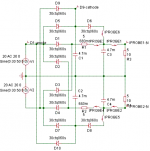
I see the snubber that way :
R x C create a time constant. If you rase R, C has to go down in value or you get a rather low time constant that may not be effective any more at the high frequency switching spike of the diode. Making R high reduces the damping of the snubber though so a compromise has to be found. I would say the lowest R that works.
I usually use no snubber at all and it works with the UF4004. A C alone without resistor will not work well i think.
I see the snubber that way :
R x C create a time constant. If you rase R, C has to go down in value or you get a rather low time constant that may not be effective any more at the high frequency switching spike of the diode. Making R high reduces the damping of the snubber though so a compromise has to be found. I would say the lowest R that works.
I usually use no snubber at all and it works with the UF4004. A C alone without resistor will not work well i think.
Most information that I have relates the value of R to the amount of energy that needs to be dissipated (Motorola, National and Rifa). In a way that leaves the C as the variable/value to calculate, but I cannot find information on how to calculate the value of R, other than the formulas found in the Hagener document.
I do agree with Joachim about the need to experiment and measure. Using 100 Ohm and 100 nF seems like a good starting point. It is in accordance with values that are found in National and Rifa papers and (the value for R at the least) agrees with Hagener's paper.
The National information that I have suggests that using a C only will suffice; it goes on to say that the power (of the energy to dissipate) will then be dissipated in the internal resistance of the capacitor, diode and the wiring. (this is for small (like ours) power supplies).
The literal text is “Capacitor shunt on the rectifier diode. Transient power is thus dissipated in the circuit series resistance”.
Last edited:
Funny, nobody has found out so far whats really going on. I see this as an opportunity to find out.
Anyway, this is a minor problem. I am just listening to a phono stage with UF4004 without snubber and the sound is great. Extremely low noise. I can hear the type of vinyl in the lead groove.
Anyway, this is a minor problem. I am just listening to a phono stage with UF4004 without snubber and the sound is great. Extremely low noise. I can hear the type of vinyl in the lead groove.
Japan patent JP2006288180
AC-INPUT TO DC-OUTPUT CONVERTER CIRCUIT
Development of Second Generation Series Power Supply Module Exceeding Battery-operated Power Supply
Rectified and smoothed DC supplying circuitry US4555751 ONKYO
POWER SOURCE CIRCUIT JP58172976 ONKYO
AC-INPUT TO DC-OUTPUT CONVERTER CIRCUIT
degawa A&R LabPROBLEM TO BE SOLVED: To provide an AC-input to DC-output converter circuit in which, in time zones (forward recovery times, reverse recovery times, time zone when voltage is applied to microarea) where electric currents do not flow through a load during diode rectification, an auxiliary power supply circuit is provided so that electric current flows through the load where electric current is insufficient, thereby improving ripples, or the like, in series power supply circuits.
Development of Second Generation Series Power Supply Module Exceeding Battery-operated Power Supply
Rectified and smoothed DC supplying circuitry US4555751 ONKYO
A DC power supply circuitry comprises an AC power source transformer with its secondary winding having a center tap; a rectifier circuit; a smoothing circuit; and a bidirectional switching circuit having predetermined threshold values, interposed in between the center tap and the smoothing circuit.
POWER SOURCE CIRCUIT JP58172976 ONKYO
:The center tap 6 of a power transformer 1 and the connecting point P of smoothing condenser 4, 5 connected in series with each other, i.e., the negative terminal 4b of the condenser 4 or the positive terminal 5a of the condenser 5 are connected through a bidirectional switch circuit 1 with the prescribed threshold value. The center-tap current is blocked by diodes D1, D2 in the range that the voltage difference between the connecting point P of the condensers 4, 5 and the center tap 6 does not exceed the threshold value of a bidirectional switch circuit 11.; The secondary coil current of the power transformer, the condenser current and the center tap current become only the amplitude information and do not contain signal frequency component.
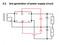
Unfortunately this 6 terminal black box is not described in detail.
http://www.net1.jway.ne.jp/nagaokm/eparts/AESpaneleng.pdf
Lots of claims, no real explanation