Up and running.....
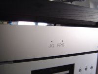
Finally, the finished FPS is up and running in my system, with the final power supply and everything adjusted and assembled (more details in the next posts).
The first impressions after listening to the fully warmed up phono stage were reinforcing the previous comments: Excellent detail down to the last microgroove, excellent bass - deep and strong, tonal very good balance, and no noise. Just fantastic.
My other phonostage is a Pearl II which is a single-ended JFET design, followed by passive EQ and a gain stage at the output. It is good as well, but no match to the FPS for tonal balance, detail, or noise. Initial comparison though was that it was a bit more involving, probably due to the "warmer" sound with a little bit more K2. No going back, however...
And, it fits well with my system as you can see ;-)
Attachments
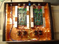
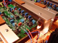
Here some more details on my build. Attached picture shows an overview of the phono stage boards in the box.
The box is made from wood, covered with copper foil on the inside. Front, top and back are 4mm aluminum. That leaves next to no magnetic shielding on the bottom side but since there is nothing in my rack and no cables, just a CD player (with no power when listening vinyl) with a thick top plate I figured thats ok.
The two PCBs are sitting in separate "chambers", and below them are the two dual shunt regs (modified salas "simplistic"). The brown patches on the aluminum frames are felt damping, that will contact the top plate (which itself is damped as well) and so the case does not vibrate.
Forgot to mention: I measured the shunt reg's output impedance to be 4mOhm (!)......
Attachments
Last edited:
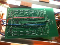
As mentioned earlier, I have modified the power supply layout on the PCB. The connections were on the input side, and in my build the shunt regs are on the output side, so I added some braces on the bottom side and connected the cabling there. The (black ) ground wire is going to the star ground at the input side, though.
Attachments
The PCBs are located in copper foil "bath tubs", and hanging from the frames with springs, in an effort to remove vibrations. Not sure it does a lot but it was fun - I even cannibalized 8 ball pens used for advertising from our company (don'T tell my boss!) for the springs.....
Attachments
I spend a lot of effort on the grounding scheme, basically implementing a star ground at the back plane (under the blue pot, hard to see). The copper "bath tubs", the PCB ground connections, the input and output connector ground connections are all coming together here, as well as the copper foil from the case.
The power supply ground is going through its connector (not visible here) on to the shunt regs and then on to the PCB, and to the star ground from there.
The power supply ground is going through its connector (not visible here) on to the shunt regs and then on to the PCB, and to the star ground from there.
Attachments
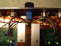
By the way, the blue pot is a Bourns conductive plastic pot (1K + 10Ohm metal film), used for adjustable loading impedance. I know opinions differ, especially on the type of resistor used at this point, and I am considering to change it at some point to a fixed resistor. Right now I want to understand better the sound impact of different values.
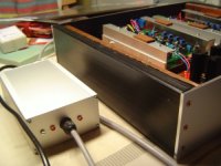
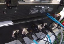
This picture shows the connection to my player and preamp, with symmetrical cables and XLR connectors. Note that the ground connection is not a screw but a banana plug, I think that is a much better connection.
The blue cables are the input cables, and the black cables go to the line stage.
The blue cables are the input cables, and the black cables go to the line stage.
Attachments
Last edited:
On the adjustment, I adjusted the shunt regulators to about twice the load current, and the output voltage to +/-12V as precise as I could. I then let it warm up for an hour or so, to re-adjust, and the supply voltages had drifted a little bit but not much.
The opamps' offsets (see earlier posts in this thread) are adjusted so they are "in the corners", each one of them sitting at + or - 2V DC at their outputs, so their tendency to drift will not impact the servo or something else.
It needs a good half hour or so before it is kind of settled, so Joachim's recommendation to leave it on all the time is good. It will consume around 30W (almost half of that is in the phono boards), considering heatsinks on the opamps.....
hope you like it!
This is really a cute one.hope you like it!
What will be the cost if anything is said and done ?
good question..... how much for the hours of work? the material is not that expensive. the kits for the phono PCBs over at pilghamaudio.com were 270 euro, the shunt regs, power supply and case probably another 200 euro or so, all in all maybe 500 euro material. Not that expensive really, comparing it to much more expensive commercial units.... except for the hours, of course. And, I can'T claim that my build quality is as beautiful as the commercials!
Hesener, this is a much more sophisticated build then i expected. You did everything you could to make it sound good. I am very happy when i see it. I have two questions :
1 : could you please measure the voltage over the gain setting resistors between the input Fets ? It is the low value one, around 2 Ohm.
2 : could you draw a schematic of the modified Salas ? I have sometime trouble when i use it so i can learn here something.
P.S. you can cool the opamps of cause. There are some cooling fins that fit. I send a photo. I am of cause very proud that you prefer it over the Pear that has a good reputation. I find single ended Fet stages just a little high on distortion, even when they are cascoded. Yes, it must be the K2 that adds that kind of warmth. It can mask detail though.
Thanks for your nice comments, and of course for the nice design that enabled this in the first place!
Will measure the voltage tonight when I get home. This should reveal the current in the input stage, right?
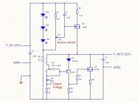
On the shunt regulators, attached is the schematic for the positive regulator. The negative regulator is the same, except for the reversed polarity of the MOSFETs, LEDs, diode and bipolar; otherwise identical.
What kinds of issues do you see with this regulator? Just to point out three things I implemented here:
1) the current source is a degenerated MOSFET, that allows for a nice point for measuring the current, has excellent noise behaviour (much better than LM317 - I tried), and lower voltage drop (the LM317 needs around 3V to start operating properly, this one works at 1V or less voltage differential - 2..3V is better though)
2) The diode in the emitter of the PNP increases the drain voltage of the JFET used as constant current source, making the reference voltage more stable
3) R6=3k3 is on the high side, the current starving for the PNP gives a lowish gain, which combined with the Q3 gain is high enough but still stable.
One issue that might happen is oscillation around Q3, but that can be fixed with R8 (not needed in my design) or a small capacitor from gate to drain (100pF or so).
The temperature stability is not great, as I pointed out in the original "simplistic" thread, due to VBE of the PNP decreasing with temperature, and the MOSFET's positive tempco (at least at these lowish currents). It is not helped with the additional diode.
But the drift is not large, and it could be fixed, but then I thought so what. Adjusting the output voltage after thermal settling is good enough. Of course, 10-turn pots for both the current and the voltage are advisable, especially for the current as the adjustment is quite sensitive.
I did measure the output impedance of the shunt regulators with a electronic load that can sink a DC and AC current, and the output impedance (= noise voltage / AC current) was 4mOhm flat from 20Hz to 22kHz. Low and flat, thats what we want right? (in this case at least ;-)
Will measure the voltage tonight when I get home. This should reveal the current in the input stage, right?
On the shunt regulators, attached is the schematic for the positive regulator. The negative regulator is the same, except for the reversed polarity of the MOSFETs, LEDs, diode and bipolar; otherwise identical.
What kinds of issues do you see with this regulator? Just to point out three things I implemented here:
1) the current source is a degenerated MOSFET, that allows for a nice point for measuring the current, has excellent noise behaviour (much better than LM317 - I tried), and lower voltage drop (the LM317 needs around 3V to start operating properly, this one works at 1V or less voltage differential - 2..3V is better though)
2) The diode in the emitter of the PNP increases the drain voltage of the JFET used as constant current source, making the reference voltage more stable
3) R6=3k3 is on the high side, the current starving for the PNP gives a lowish gain, which combined with the Q3 gain is high enough but still stable.
One issue that might happen is oscillation around Q3, but that can be fixed with R8 (not needed in my design) or a small capacitor from gate to drain (100pF or so).
The temperature stability is not great, as I pointed out in the original "simplistic" thread, due to VBE of the PNP decreasing with temperature, and the MOSFET's positive tempco (at least at these lowish currents). It is not helped with the additional diode.
But the drift is not large, and it could be fixed, but then I thought so what. Adjusting the output voltage after thermal settling is good enough. Of course, 10-turn pots for both the current and the voltage are advisable, especially for the current as the adjustment is quite sensitive.
I did measure the output impedance of the shunt regulators with a electronic load that can sink a DC and AC current, and the output impedance (= noise voltage / AC current) was 4mOhm flat from 20Hz to 22kHz. Low and flat, thats what we want right? (in this case at least ;-)
Attachments
Ok, that is a version of the Salas i do not know. I had trouble with oscillation in one case. I think i used the Mesmerize. Maybe i just loaded it to heavy with Elcaps but i also tried decoupling with resistors and it did not help. On another stage it worked well.
Yes, the measurement on the gain resistor gives the idle current in the input stage. It does not matter much. Non matched Fets have no effect on the noise performance ( Scott Wurzer pointed that out ) and a unbalance in Gm does not effect distortion much ether because of the feedback structure. I am just curious. The amount of current that flows totally of cause gives a clue of how low the voltage noise is.
Yes, the measurement on the gain resistor gives the idle current in the input stage. It does not matter much. Non matched Fets have no effect on the noise performance ( Scott Wurzer pointed that out ) and a unbalance in Gm does not effect distortion much ether because of the feedback structure. I am just curious. The amount of current that flows totally of cause gives a clue of how low the voltage noise is.
Interesting point... loading this regulator with large capacitors causes a phase shift at higher frequencies, hence oscillation.... Did you try and put resistors in series with the cap (to increase ESR)? It's counter-intuitive but works well. Audio Research used a similar trick, albeit for other reasons, in their tube line stage power supply (forgot the model, I think it was the LS25).
In my phono stage the 1.5uF at the output is all I use! It feels strange to NOT have big caps there, and when I unplug it goes off immediately..... never had that before.... but the listening results and also the measurements indicate otherwise.
I remember I did measure the voltages across the 2x47ohm resistors in the current sources, both sitting at about 400mV, so 17mA. But I will take another look.
That transfers into a noise resistance of ca.15 Ohm including the feedback resistor. That is 0.5nV/qHz, right on target. That gives a signal-noise of ca.-77dB unweighted. So we have more then -80dB weighted. The only stages i know that are better have 0.3nV/qHz but they are single ended and do not have the advantage of balanced. The other issue is that the Johnson noise of the cartridge itself adds to the noise. Say it is 10 Ohm. Then in one case we have 25 Ohm
( FPS ) and in the other we have 15 Ohm ( physical limit ). That reduces the theoretical advantage of the single ended ( with the same amount of the same input devices with the same idle current ) to less then 2dB. I can life with that and the single ended will most likely pick up more hum and that is annoying too.
( FPS ) and in the other we have 15 Ohm ( physical limit ). That reduces the theoretical advantage of the single ended ( with the same amount of the same input devices with the same idle current ) to less then 2dB. I can life with that and the single ended will most likely pick up more hum and that is annoying too.
But the drift is not large, and it could be fixed, but then I thought so what. Adjusting the output voltage after thermal settling is good enough. Of course, 10-turn pots for both the current and the voltage are advisable, especially for the current as the adjustment is quite sensitive.
I did measure the output impedance of the shunt regulators with a electronic load that can sink a DC and AC current, and the output impedance (= noise voltage / AC current) was 4mOhm flat from 20Hz to 22kHz. Low and flat, thats what we want right? (in this case at least ;-)
Use LEDS instead of Norton Vref if better drift is desired, but it can be inconsequential. You skipped capacitor filtering the Voltage reference resistor and trimmer on purpose? That could be an important aspect. Your build works well for Zo in its simple form, congrats.