I tested the Stereo Anti RIAA with my JG-Self preamp hat i keep as a bechmark.
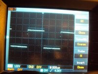
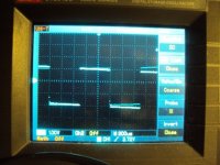
The right channel Anti RIAA is shown with the right channel and the left channel Anti RIAA is shown with the left channel. This measured very similiar from left to right and also similiar to my older Anti RIAA. I slight missmatch of input impedance of the phonostage does not make much difference because the total impedance of the Anti RIAA is nearly 1MOhm. I expected that. For the 1nF i used a COG-NPO ceramic. I have a bag of 100 pc. and i was really surprised how close they match. I found a perfect pair right away and the worced i measured had 0.98nF. I whould not hessitate to use them even in critical applications. Unfortunately they are not availlable in high values.
Shown is a 1kHz squarewave. The resistors are 0.1% Dale and Beyschlag metalfilm and the other caps are 1% silver mica.

I have some trouble uploading the pictures although i compressed them.
I try later.
The right channel Anti RIAA is shown with the right channel and the left channel Anti RIAA is shown with the left channel. This measured very similiar from left to right and also similiar to my older Anti RIAA. I slight missmatch of input impedance of the phonostage does not make much difference because the total impedance of the Anti RIAA is nearly 1MOhm. I expected that. For the 1nF i used a COG-NPO ceramic. I have a bag of 100 pc. and i was really surprised how close they match. I found a perfect pair right away and the worced i measured had 0.98nF. I whould not hessitate to use them even in critical applications. Unfortunately they are not availlable in high values.
Shown is a 1kHz squarewave. The resistors are 0.1% Dale and Beyschlag metalfilm and the other caps are 1% silver mica.
I have some trouble uploading the pictures although i compressed them.
I try later.
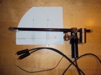
I got an Artemis arm from Frank Schröder. Seldom have i seen such a beautifull and pureposefull piece of Audio Engineering since the heyday of Quad. I think Frank was the first who used a freely rotating headshell. The arm is from Kingwood, a rare palisander type. The bearings are ceramic hybrid with very low friction. Frank also included a downpreasure fineadjustment that you can see at the end of the arm. Antiskating is magnetic.
Attachments
This Anti RIAA can also be put behind a CD or better SACD player with sufficiently low output impedance and then the player can drive the phonostage. I do not say that this is a fidelity test of any kind but a sraight wire bypass could be quite telling at least about the tonal balance.
Is that analogous to Dennis Colin's ''intrinsic fidelity test''?
Yes, Dennis Collin calls it that way. When this sounds absolutely the same then putting the CD player directly into the linestage the quality of the whole chain must be quite poor i think. I will try it and report.
I did not have many ideas concerning new topologies recently. Actually i am busy bringing some circuits of mine on PCB and working on the ones that already have a PCB to finalise them. I have good new from Ward Maas. I found a way to solve the differential offset problem in the FPS published in Linear Audio Volume 0. Ward is working on a new PCB layout and i will publish the finalised version soon.
Yesterday i had an elightenment. What the world needs is another buffer. Actually i need a new buffer. I usually use my modified JLH buffer or the open loop buffer i have shown here. Both have being critisised because they need a second stage. The modified JLH has bipolar transistors in a lokal feedback loop and the open loop buffer has aditional bipolar transistors with the well known biasing problems. Here i present a single stage buffer that is an enhancement of the well known Curl or Borbely JFet buffers. I have cascoded the input transistors and i return the base current to the sources by way of a Hawksford cascode. Drawn a bit different this could be the input of a phonostage too.
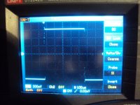
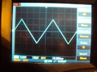
I had only low Idss 2SK246 so i simply paralleled 3 to make the current draw similiar to a 2SJ103BL. I still have some 26mV offset. That could be solved with a trimmer at the output and then replacing the values with fixed resistors. Also the current through the Leds could be trimmed alternatively. This circuit is very fast and works in class A to about 8mA. Even at 20Mhz, my measurement limit, i could not see any drop in gain. The circuit has a 3dB overshot at 16Mhz so i installed a lowpass at 10MHz. Shown is a 100kHz squarewave with the filter installed. I could not drive the circuit into clipping with the maximum 20V P-P from my generator even with a low + - 12V supply. Shown is a triangle wave i use for watching clipping with 20V P-P input.
I did not have many ideas concerning new topologies recently. Actually i am busy bringing some circuits of mine on PCB and working on the ones that already have a PCB to finalise them. I have good new from Ward Maas. I found a way to solve the differential offset problem in the FPS published in Linear Audio Volume 0. Ward is working on a new PCB layout and i will publish the finalised version soon.
Yesterday i had an elightenment. What the world needs is another buffer. Actually i need a new buffer. I usually use my modified JLH buffer or the open loop buffer i have shown here. Both have being critisised because they need a second stage. The modified JLH has bipolar transistors in a lokal feedback loop and the open loop buffer has aditional bipolar transistors with the well known biasing problems. Here i present a single stage buffer that is an enhancement of the well known Curl or Borbely JFet buffers. I have cascoded the input transistors and i return the base current to the sources by way of a Hawksford cascode. Drawn a bit different this could be the input of a phonostage too.
I had only low Idss 2SK246 so i simply paralleled 3 to make the current draw similiar to a 2SJ103BL. I still have some 26mV offset. That could be solved with a trimmer at the output and then replacing the values with fixed resistors. Also the current through the Leds could be trimmed alternatively. This circuit is very fast and works in class A to about 8mA. Even at 20Mhz, my measurement limit, i could not see any drop in gain. The circuit has a 3dB overshot at 16Mhz so i installed a lowpass at 10MHz. Shown is a 100kHz squarewave with the filter installed. I could not drive the circuit into clipping with the maximum 20V P-P from my generator even with a low + - 12V supply. Shown is a triangle wave i use for watching clipping with 20V P-P input.
Attachments

Hi Salas ! Yes, i think that is what he ment. It should sound indentical with anti RIAA and phonostage against a direct feed into the linestage, so it is "transparent". I did not find the time to try that so far. When the stage he published in AudioXpress does that trick why am i trying here ?
Hello Sam ! Please wait for a while. I did some important improvements. I send you the circuit soon. It can now drive up to 50mA in class A. I do not know why i am so mesmerised by buffers but they make a big diffence in my system. In the meantime i can steer the sound from warm and wooly to dynamic and tight without changing anything else in the system.
Hello Sam ! Please wait for a while. I did some important improvements. I send you the circuit soon. It can now drive up to 50mA in class A. I do not know why i am so mesmerised by buffers but they make a big diffence in my system. In the meantime i can steer the sound from warm and wooly to dynamic and tight without changing anything else in the system.
Today i had a very strange idea. Actually is is not my idea but i turned it upside down and turning things up side down i can my friends tell me.
A ( presumably older ) gentleman published a phonostage here he calls "Edgar". First i was totally shocked. He did the 75usec passive right after the MM cartridge ! And how !
He took a 680kOhm resistor and a matching cap to ground. Then it went into a TL072 on plus-minus 5V supply. This must be the lonesome record for noise and low overload margin but he was claiming it sounds great. When i thought more deep i found that here is a new oportunity. What whould happen if i do that with MC cartridges and instead of a cap use an inductor ? Well, it should work, so i drew together a quick schematic. I have some very nice Sowter 8mH coils in Mu-Metal so i could use them with my Titan i and a resistor of around 100 Ohm. One ceveat : this will only work with a certain cartridge and the inductance being low in low output Moving Coils the ohmic resistance is the parameter to watch. I simmed my Titan i with 6 Ohm and 5uH. The Sowters have an ohmic resistance of some 6 ohms too so aproximately 100 Ohm loading should work. The schematic i show is a one stage design and that will have troube. The Opamp needs to have 60dB of gain at 20kHz so not much is left for distortion reducing feedback. The solution whould be a two stage design with gains of 30dB each and that is what i will try. I can now oversee that i will not finish my tube RIAA for ETF but i may throw something together along this lines. It´s a sad and beautifull world ( Lucky Luke ).
Attachments
I am sure they had it, but wouldn't be done with resistors due to huge Ren for a practical capacitor size combination. Then its the quality, shielding, sourcing and cost for the special coil. You know, comes across like non practical at all not to do the HF bit later on in circuit. But you having the coil, if it will be no hum (consider the signal level there), you can tell us if its relaxing the sonic scape, by entering a level HF from the start. Surface clicks and pops not firecrackers and violins from heaven? Or a hum disaster? J will tell!")
P.S. What is the DC resistance of the coils you got by the way? It will be Ren, all of it.
P.S. What is the DC resistance of the coils you got by the way? It will be Ren, all of it.
I thought a little bit further how a passive inductive RIAA could be made.
We already learned that to get low distortion we have to split the gain. My example shows a 50/50 split so that each stage has about 30dB gain at 1kHz for a total of 60dB. Keeping the RIAA component values we have to raise the feedback resistor in this case to 100 Ohm.
This creates a new noise source. One option is of cause to use smaller resistors and bigger caps. On the other hand the poor opamp can not drive more then 600 Ohm clean unless we use something like a LME49713 that drives 100mA or we donate a buffer. Anyway, that 8mH Sowter ain´t cheep eather. And again serendipity stroke a match.
What about our infamous Phonoclone topology ? Well, considering that the DC resistance of cartridge and coil is 10 Ohm in total we end up with only 0.75mH. That is managable and afordable i thought ! Anyway, see my basic schematic. I am working on the details.
On the other side of the moon i have moved my cap tester experiment from the Blowtorch thread to here. John Curl was so skocked that i use a high DA Silver Mica as highpass cap right in front of my main tubeamp that i thought i had really commited a sin. I have now build a switchbox and a buffer to setup a little listening contest. See what i have so far on the Blowtorch thread. I will not repeat the information here including the schematics. Again more load on my wide but not so strong any more shoulders. One guy has already requested that i test his fav cap. Somehow so much trust makes me proud but :
"What have i done to my song ?" Melanie
I have the cap tester up and running and the good news is that i can not hear any nasty clicks and pops when i am switching besides the mechanical sound it makes. Do i hear differences and how do the caps sound against the bypass ? This is too early to tell and i whould rather like that others listen because they do not know what´s inside the box. To make it even more difficult i simply could use the bypass as a fifth option without telling the listener that this is the reference. Whatever comes out here, i will not do a ranking and i will not give "points", "stars", "highlights" or whatever. This will only represent subjective impressions only valid in the context of my system. I have no aspiration to be the Tony Gee of low level capacitors. OK, i promissed to measure the "worsed" against the "best" in the end if i can find any objective differences. What i already did, also to check the switchbox for functionallity, was feeding in a 1MHz squarewave. Yes, the buffer is that fast. A 100kHz square just comes out as a more or less perfect square. And guess what : all 4 caps of wildly diffent construction i set up for the first round gave absolutely the same picture. The bypass looked the same with one little exeption and i am a bit clueless at the moment what that is but i will tell you more next time.
Not surprising- if a cap is terminated with a high impedance, one would expect that its characteristics/flaws/what-have-you would be swamped. That's what I've found as well- with a 1M load, the cap box I built shows no measurable difference between Teflon and NP electrolytic. Audibly, any differences are very subtle, certainly not "jump out at you obvious."
An asymmetrical pulse will bring out DA between virtually any electrolytic and Teflon. This was measured by me up to 50K ohms and there is no reason that 1 Meg would completely eliminate it. For further info, please look at the cap article by Walt Jung and me from 1985. It is almost impossible to measure with pure sine wave analysis, however. A computer simulation will show this as well, that it takes the asymmetry of the test signal to bring the error out into the open.