SY is on track, however, with the loading of the caps. This buffered output is not very realistic in the actual use of an audio cap. How often can we have 1 meg input impedance? Very rarely. Volume controls get noisy at 1 meg, filters too. If you want non-linear distortion measurement, you have to drop some voltage across the cap. This implies a realistic RC time constant, such as 10K-50K for realistic testing.
Linear error or DA will NOT completely go away, even with 1M loading, but it will not be as much in magnitude as it would be with a lower impedance load.
Linear error or DA will NOT completely go away, even with 1M loading, but it will not be as much in magnitude as it would be with a lower impedance load.
So a high impedance loading swampes cap diffences. Is that one reason that Mark Levinson used 1MOhm impedance in the Cello equipment and now at Daniel Hertz ?
I found out some time ago that high impedance buffered Opamp sound much better but i thought because of other reasons I will not expole that here at the moment. I will look at the Curl and Jung paper again, what kind of signal they used.
Smaler cap values may have also less probems with ESR, inductance, mechanical shock etc. Could that be one reason that high impedance tube equipment sounds better to some?
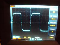
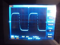
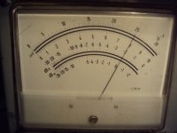
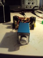
Anyway lets explore something i found. Feeding in a sine, triangle or square into the bypass and then into any of the 4 caps i installed i found a small jump in level athough the shape of the signal was not visually altered. I then checked the level difference with my tube meter and found that the bypass gave around 0.2dB more level. I checked that at 1kHz, 100kHz and 1MHz and it was always the same. I whould have understood that better at lower frequencies when the high pass action comes into play. So the straight bypass may not be a good refference because the ear has a tendency to prefer the louder signal. How well level has to be matched seems to have changed over the last 40 years. I learned in the 70th when i studied Telecomunications that 3dB is "just well audible" and 1dB is " barely detectable". When i now read for example the literature about the Heron Phonostage or trust what Siegfried Linkwitz is currently experiencing with his Orion 3.2, then the threshold is currently identified at better then 0.2dB. Where does that lead us ? Is that again the old argument about easy detection of small differences in LINEAR distortion ?
Anyway, here are the scope shots and the meter readings. Bypass, cap, from left to right.
I found out some time ago that high impedance buffered Opamp sound much better but i thought because of other reasons I will not expole that here at the moment. I will look at the Curl and Jung paper again, what kind of signal they used.
Smaler cap values may have also less probems with ESR, inductance, mechanical shock etc. Could that be one reason that high impedance tube equipment sounds better to some?
Anyway lets explore something i found. Feeding in a sine, triangle or square into the bypass and then into any of the 4 caps i installed i found a small jump in level athough the shape of the signal was not visually altered. I then checked the level difference with my tube meter and found that the bypass gave around 0.2dB more level. I checked that at 1kHz, 100kHz and 1MHz and it was always the same. I whould have understood that better at lower frequencies when the high pass action comes into play. So the straight bypass may not be a good refference because the ear has a tendency to prefer the louder signal. How well level has to be matched seems to have changed over the last 40 years. I learned in the 70th when i studied Telecomunications that 3dB is "just well audible" and 1dB is " barely detectable". When i now read for example the literature about the Heron Phonostage or trust what Siegfried Linkwitz is currently experiencing with his Orion 3.2, then the threshold is currently identified at better then 0.2dB. Where does that lead us ? Is that again the old argument about easy detection of small differences in LINEAR distortion ?
Anyway, here are the scope shots and the meter readings. Bypass, cap, from left to right.
Attachments

SY is on track, however, with the loading of the caps. This buffered output is not very realistic in the actual use of an audio cap. How often can we have 1 meg input impedance?
With tubes or FETs, just about anytime we want.

John, as far as i can see you used a negative going step in the 1985 cap measurements.
Since the late 70th when i met Mr.Manger i do step response measurement on speakers too but usually with a positive going step. In the early days with an analog step generator and scope and later with impuls response measurement and convolution first with MLSSA and now with a log chirp in Praxis. The most basic way whould be just to connect a battery and then switch it of. It could be argued that a real step is more taxing then using a low crest factor signal and then postprocessing. Mathematically it´s all the same.
Since the late 70th when i met Mr.Manger i do step response measurement on speakers too but usually with a positive going step. In the early days with an analog step generator and scope and later with impuls response measurement and convolution first with MLSSA and now with a log chirp in Praxis. The most basic way whould be just to connect a battery and then switch it of. It could be argued that a real step is more taxing then using a low crest factor signal and then postprocessing. Mathematically it´s all the same.
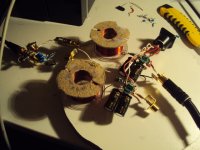
I build the input stage of the Simple Inductive Passive RIAA. I decided to do the mid-bass equalization right in the inverted input stage. The 1kHz gain is setup as 30dB and i will add a second inverted stage with 30dB of gain. Yes i know, it looks like Arte Powere in the High End Emergency Room but i did not have a fitting case for the rather big coils so i build it right in the open on a chip board plate. Heck, the ETF begins in less then a week and i whould like to show something unusual concerning phonostages. I measured it and it amplifies and i could squeze out a half decent squarewave at 1kHz. The level though is very small because i modified my invers RIAA to have an output impendance of 6.8Ohm. That way the input signal is very small and the aplification is only 30dB.
Lets see what happens when i add the second stage. If it works, i will publish a schematic.
Lets see what happens when i add the second stage. If it works, i will publish a schematic.
Attachments
JG - did you by chance check out my thread on an inductive RIAA preamp that I posted about a year or so ago? It looked possible to do the preamp stages with a couple of jfets and a moderate value of inductance, attainable using gapped ferrite pot cores. I haven't had time to try it yet, but it may serve as food for thought. An advanced title search with "inductive RIAA" as the search parameter appears to be very specific....
Yes, i have gone over it and found it very interesting. I have to reread it now. Actually i have build an active inductive RIAA and posted it here. I got very low noise and the sound was particular "open" in the midrange. My friend Jürgen Ultee builds an commercial inductive RIAA called "The Grail" for Van den Hul that got very good reviews over here.
He uses Epcos open frame ferite inductors made from a special material. He told me that Van den Hul had to buy 20.000 cores because after he finished the design they stopped production and this was the minimum quantity for another roll. This much about an industry that has lost the interest in high quality audio a long time ago here. Ones Saba, Grundig, Telefunken etc. made world class products and the reason was, when i talk to older senior designers, that they had access to very good quality passive parts.
Now High End Audio is a boutique busyness.
Back to my Simple Passive Inductive RIAA, i ran into some offset problems. I am using the ADA4898 at the input because it likes to drive low value resistors. "Conventional" Phono Clone topologies use a feedback resistor not much smaller then 1kOhm but this whould give me too much gain in the input stage. The DC gain of my circuit is around 300 and the input offset voltage of the ADA4898 is specified as 20mV typical and somewhat over 100mV maximum. I landed at around -8V so this is in the ballpark. I will try a compensation resistor bypassed by a big Elcap. I could use a servo but time is short to ETF and this is only a prove of concept. If it humms i have some MU Metal sheets but i will not go into any length to win a new world record here in the few days that are left.
The idea to do the mid-bass EQ in the second stage works. The offset i get is 0.3V now and a good cap at the output is all i needed to manage that. The 1kHz square wave looks only half as bad as i expected. A very slight ultrasonic overshot and a response that leans just a bit to deeper regions. I can live with that without tweeking. See the schematic. I also will post a screenshot later.
Why is R13 so small you could ask ? First it does not contribute much noise that way and second the ADA4898 can swing 40mA clean so is able to do 6V into 150 Ohm and i think that this is more then enough considering that the signal is down ca.20dB @ 20kHz by action of the input coil. The second Opamp is an OPA134 i rescued from the waiste bin. It is not my absolute favorite but i think in this inverted configuration it is fine and being a Fet input amp, offset is low.
Why is R13 so small you could ask ? First it does not contribute much noise that way and second the ADA4898 can swing 40mA clean so is able to do 6V into 150 Ohm and i think that this is more then enough considering that the signal is down ca.20dB @ 20kHz by action of the input coil. The second Opamp is an OPA134 i rescued from the waiste bin. It is not my absolute favorite but i think in this inverted configuration it is fine and being a Fet input amp, offset is low.