I am building a second Hypnotize to supply another experimental stage. I need 2 x 17V.
I mounted the Fets on bigger finns this time. That makes some mechanical trouble but i can solve that. I will use 6.8 Ohm set resistors this time. I have already mounted the two Leds with the test resistor. I use a 250 Ohm because i did not have a 200 Ohm. I have to go though Salas text ones more to not make any mistake. I start to understand this circuit better but not in full and i am really fascinated that it gave such a good improvement in sound over the LC Audio. I am using a split bobbin frame transformer with 2 x 18V AC.
I have used that transformer for a standart 2 x 24V supply before. See picture.
I did not know you got a few in that Fest.... Handy little boards. There aren't any more around, and they will not be again. The Blue they snapped it up also fast from the US GB manager... One guy put a blue up a wall frame to stare at it!
")
Its easy Joachim, go directly to the example steps copied from the guide here for your convenience:
4. Example
I want to make a +/-15V shunt reg for my preamp. Its steady state consumption is +/- 75mA. I have this oddly named pitch black board after some American Armenian NuMetal band's song that I got on a GB from some Tea-Bag named guy. What the **** do I have to do? I like Cher's see through dressed videos, don't care about SOAD, but beyond that I am clueless.
Take it easy. Read all the above text **You know already about the leg trick and the residual leds and resistor position in that text Joachim**. Choose trafo. Choose (7mm lead spacing) main capacitors voltage that can take it after x 1.41. Install two matched leds and 220R test resistors per side as in the pic. Fully stuff the regs part of the thing. Use 2x 33R 1W resistors in the 2x 68R places. Good for about double the needed mA example given the 1.6-2.2V/Rset (33//33=16.5R) ballpark formula you read before. Sink it USING silicone TO-247 insulation pads. Power it up.
Say you measure 70mV on the 10Rs and 6.14V out. You measure about 1.54V across the test resistors. 6.14-1.54=4.6V, its your base voltage, can't go lower. 15V-4.6V=10.4V. You need to add that part. Power it off now. Cut off the 220Rs up near the body. Toss 'em in the bin. OK. 70mV/10R=7mA. That is how much it runs in the Vrefs with those Idss matched JFETS per side that you had. 10.4V/7mA=1.486kOhm. 1.5k 1/4W will do. Install them on those left off test resistor PCB proud pins. Power on again. OK. +/- 15.1V @ 100-133mA CCS all set. If one side had weaker mV on its 10R or the vbe and Vfs were a bit unmatched, then use a small corrective resistor in series with the main 1.5k on the weak reg's side, so to match +/- Vouts. Connect your pre to it. Hey, the shunt Mosfets are running cooler now, must be sharing half the current with the load. Listen...hmmm compared to that LM317/337 you had, maybe you can ''feel more detail in music''. Naah, you can't?. Swear at Salas, Crt, and Tea-Bag that put you in the drag then. If else...Enjoy.
Attachments
I use that LM317/337 board only for convenience of voltage setting when i test a new board. Never made any critical listening with it. For listening i either use special high energy lead acid batteries, buffered, or the LC Audio Low Noise supply, double mono, common mode choke, Pi filter. Your hynotize did better then any of those. Why are the Hynotize Boards not availlable any more ? They really come in handy for me. I could make some when i had a layout. It would be even more convenient to have them without the buffer section. I hate to cut that part of. I do not like to destroy things.
The 317/337 funny line was there in the example always, copied together.
It was never more than a communal project and a GB. So they got given away to subscribed guys. Then they wanted another run for those who missed out so we thought we make a heavy copper plated through special edition in blue as my avatar's color having more filter caps, TO-220 diodes, positions for 5W Iset Res, big film cap bypass for Vref. So it can be handy for running heavy. If we make again under enough requests it will be the blue again. Black is original and collectible. Keep em.
V1.2 is in another league really, only for advanced dead bug and perf board guys, layout masters and oscillation hunters. You will see when you will make. There will be Kelvin connections, tuned Zobels to load, CFP intimate pair, and many other sagas.
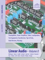
Actually in the beginning of this tread i made a major efford to build theV1.2. I had given the circuit also to Brian Daily in the US and he started on a 75 Ohm HF layout. I wanted to do the dead bug version and then everything got different. Brian got busy with other things , me too. Now i am happy that i did not imediately walk that road. It was more important that several of my circuits matured and i am now at that point. I do not post that here but some of the new circuits have been put through extensive simulation and i now understand each detail and function of the circuit to arive at optimum values. Passiv components have been listened too, constuction techniques tryed. I am much more confident of what i do then i was a year before. I think now is the time to look into the periferals like PSU, cabinet, PCB etc. In fact several of my designs are already on PCB boards, some of them shown here. The Discrete INA is the most fully mature design and i describe it in detail in Jan Diddens new Linear 0 compilation. It shows details not published here and is called FPS there. Sigurd Ruschkovki did a complete circuit analysys end the technical data of that design are simply perfect. I am just talking to Jan if he can provide a download of that analysys but you can imagine that he is very busy too. Why got this world so fast ? I have a feeling when i not contantly invent the competition is eating me up but i think that is totally subjective. A half kit will be availble from Pilgham Audio and you can see a bit of the internals on the front cover of Jans Book.
Here is the front cover and you can see part of the circuitry. Layout is by Ward Mass that worked as a young engineer on the development of the CD at Phillips. I think he did a wounderfull job and he calls it "Elektronen Autobahn". It is strainge and wounderfull when you see your own work through the eyes of other people you respect.
Attachments
Hello Joachim,
I have sent the money for the first Linear Audio yesterday to Jan Didden
Cannot wait.
I've started yesterday with listening tests of the PSU's for the FF2010 Linestage. First have been the Hypnotize board and a Shunt PSU from China.
Today I will rise the current of the Salas board, let's have a listen.
Will post pics over the weekend.
Wkr
SAm
Thanks Sam that you wil do the hard work and listen to PSUs. You will not regret to get this book. I have never seen such a splash of well written material from the most ( if not all, give Jan a note if you have something intesting to contribute )prolific designers in the field. I have not seen the other articles but for my work the new Self compensation and the Cordell distortion magnifier should be interesting.
periferals like PSU
In my simplistic point of view any audio cct is an ac modulator of a dc power source. If that holds some water, then the psu quality can go up to 50% of the total quality depending on the sensitivity of the modulator, but it will always be the strongest strategic partner, with obvious contribution.
Yes, Salas, many people say so. By the way i have more listened to the Hynotise and the strage effect that depth got better but height was forshornened is gone. For example "Mysterioso" on the Till Brönner Album "Till Brönner in Rio" i can hear Annie Lennox 3m up and 3m away now, much as it was before but the improvement in depth perspective is still there. This is most wellcome because depth perspecticve is the most problematic issue in my new room. The new room is over 7m wide but only 4.25m deep so i have to sit quite close to the speakers and there is not much space ( 1.2m to 1.7m depending how close i sit ) behind them. My old room ( i lived in a rented house before i build my new house 7 years ago ) was less wide but deeper and on some recordings i coud here sounds 20m away and still well focussed. That was amasing.
I also recocnised that with the Hypnotize immaging differs much from record to record, so on some recordings like "Hellen Merill in Tokyo" i can here her voice moving from left to right plus-minus 50cm. I did not hear that before. With the LC Audio most voices came from high up and you had the impression you sit in the 5th row at a life concert and look up to the stage. This is not any more the case and on some recordings the voice sounds deeper where it should be at around a height of 1,6m like in "Lois Armstrong and Duke Ellington together for the first time" where the voice with my old supply had the stage effect. when now his trumpet sets in it comes from 1 to 2m deeper. I think the Hynotize diffentiates more, because on some recordings i still get the stgae effect and on some not any more. The reason i whould like to use the Hynotize as my benchmark in the future is that it is fast and inexpensive to make, has very good sound and can be directly wired to the circuit so circuit plus PSU is now a unity. The V1.2 is surely better but i need something one notch down because with a too good supply, small problems in my circuits will maybe be swapped more. Maybe i am wrong and an even better supply will bring out diffences in the circuits even more.
Anyway, i look now into PSUs and my plan is to have a good handle on that problem in around 4 weeks. I will stay with the CCS-Shunt topology with one exeption. The FPS from the Linear Audio book has the Didden-Jung Superregulater on it. Whould be interesting to use a CCS-Shunt in comparison.
Remember I said 2 days for more?
You can make a V1 like Hypno with remote sensing and variable output at least for your everyday needs. V1.2 maybe is IMHO 100% better subjectively at least in low psrr head amps. CCS & shunt comes from tube stabilizers in the 30's goes through Japanese Stax in the 70s, and then to a few voices in the desert. Although only the configuration says not much. Each reg in such broad topological category has its own traits. Have listened to enough reminding good series regs minus the series's top notch silence and detail. Borbely series is better than many CCS+Shunt IMHO for instance, also Jan's series is better than many. You would need 1.2 to put against series super regs so to get the ease & space plus the top analysis.
You can make a V1 like Hypno with remote sensing and variable output at least for your everyday needs. V1.2 maybe is IMHO 100% better subjectively at least in low psrr head amps. CCS & shunt comes from tube stabilizers in the 30's goes through Japanese Stax in the 70s, and then to a few voices in the desert. Although only the configuration says not much. Each reg in such broad topological category has its own traits. Have listened to enough reminding good series regs minus the series's top notch silence and detail. Borbely series is better than many CCS+Shunt IMHO for instance, also Jan's series is better than many. You would need 1.2 to put against series super regs so to get the ease & space plus the top analysis.
I know that Stax used Shunt Regulators and i owned and listenened to a lot of that stuff.
When i got to know Stax in the 70th, shunt regulators where a new concept to me and i was sold because the Stax components sounded very good. In the 90th i even made a project together with Stax for the Japaneese Radio Company. It was a multichannel loudspaeker system ( 11 channels ) that could be placed on the wall. Cabinets where not allowed to be deeper then 5cm. The original idea was that Stax makes an electrostatic tweeter for that project but Stax went through difficult time back then and eventually whent into ownership. In the end i had to do everything myself to avoid that Stax "Looses Face". I met the schedule and the project went through ok. The next encounter with Shunt PSU was equipment from Forsell, Sweden. I was the importer for many years and still have a Forsell DA converter with Shunt PSU. When i encountered Salas work i actually knew from the beginning that this will work and working it does, brilliant.
When i got to know Stax in the 70th, shunt regulators where a new concept to me and i was sold because the Stax components sounded very good. In the 90th i even made a project together with Stax for the Japaneese Radio Company. It was a multichannel loudspaeker system ( 11 channels ) that could be placed on the wall. Cabinets where not allowed to be deeper then 5cm. The original idea was that Stax makes an electrostatic tweeter for that project but Stax went through difficult time back then and eventually whent into ownership. In the end i had to do everything myself to avoid that Stax "Looses Face". I met the schedule and the project went through ok. The next encounter with Shunt PSU was equipment from Forsell, Sweden. I was the importer for many years and still have a Forsell DA converter with Shunt PSU. When i encountered Salas work i actually knew from the beginning that this will work and working it does, brilliant.
One other idea. Could we not develop a board based on the Hypo but without the buffer and with remote sensing to make it even more flexible? I then whould not have to make a PSU every time and harwire. I could imagine that many people whould like to use something like that.
Yes it will surely work, beaten path. Many diyers here have V1 with adjustable Norton Vref with or without Kelvin bridge sense connection. They make it p2p or devise their own etch. The simplistic threads are full of them. I communicated them as for DIY use only, but who knows where they might end up under the bonnet.
Ok, i will try to find the time to go though this thread. All threads about your work get rather long though. I simply would need a circuit diagram and then etch myself. Not for commercial use but for my prototyping. When i do a commercial circuit i work together with other designers that do the layout and ad a PSU. But as i already said, in 4 weeks i will be able to design a circuit myself and be more independent.
Those two should help you out. I dug em up and did sync the designations.
Up to 28Vout +/-. With 10R R1 shown circa 200mA CCS, exact current depending on LEDS Vf and Q1 Vgs, I noted the CCS formula so you can set them for current at will. Keep a 2:1 to load if able to sink.
*Its the BMW bicycle I meant.
Up to 28Vout +/-. With 10R R1 shown circa 200mA CCS, exact current depending on LEDS Vf and Q1 Vgs, I noted the CCS formula so you can set them for current at will. Keep a 2:1 to load if able to sink.
*Its the BMW bicycle I meant.
Attachments

Yep, just tweak those R6 multiturns. If you want best ppm there, sub with nice resistors after you find proper values by trimming. You can limit your DCin to 30V if your roof is 24Vout, to save some dissipation. C2 is influential for tone, choose/bypass as you know best.