Attachments
Youtube. This irks me a bit. So, I publish a lovely fresh sounding analog compressor, the clipnipper, which does not get any press. And then, ironically and annoyingly, Youtube uses the nasty cheapskate sort of digital compressor that sounds like a fuzzbox. Perhaps it is appropriate for assisting iphone speakers to play a few decibels louder than before.
That might not be the best website choice to illustrate what music is supposed to sound like--they usually screw it up. Maybe SA Stereo Tool filter can remove some of the damage?
Or, an analogue option. . .
It is a strange thing that some amplifier topologies can post process a little bit, to somehow remove some of the digital fuzz without removing the music. A shunt comp preamp might could manage an artificially deep noise floor. Likewise, but backwards, a high gain old Miller amp could manage a dynamics expansion if the speaker return direct-connects into the amplifier board, to jolt it, precisely, and on purpose (a mild form of Armstrong Boost, which is so much fun and not always mild). In combination, and despite the probably excessive system gain, I wonder if the pair could remove the YouTube "digifuzz" distortion or at least make a more convincing and less compressed presentation? So far, so good. But it would have been easier if Youtube had not added yet more compression of such weird quality, as if anti-imaging or flattening (that I don't like).
And then the question:
That shunt comp preamp that could make the quiet quieter? Can it be used as the rail splitter and/or regs in power supply duties? I suppose that should be quite successful. It may be worth the parts count.
Last edited:
Dan, it sounds like you're asking for a special kind of opamp. The thing is, low treble distortion tends to mean conditional stability into capacitive loads, hence necessitating an L/R at the output. For this reason an opamp that could work both as a reg and as a preamp would require careful design. But it is an intriguing challenge. You could ask the guys here about it:
http://www.diyaudio.com/forums/analog-line-level/218373-discrete-opamp-open-design-59.html
For a rail splitter, I would use an opamp and filter it's supply pins to improve PSRR. I was going to say that opamps have worse PSRR than chip regs, but then I realized I'm not really sure about that... Maybe certain opamps would be an advantage if used as regulators, owing to their speed?
Last edited:
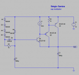
Cap multiplier
Today I was testing my shunt regulator that has a Pré-regulator, and I realize (remember) that when one use a pré-regulator there is no need for a great PSRR as the total PSRR is the sum of the pré-reg PSRR and the main-reg PSRR.
And, I want to design a new regulator for my headphones amplifier, that works in class A and consumes 50mA per channel.
So, I went to ltspice, and try to improve the output impedance of the Keantoken multiplier.
This is what I have right now. It uses the FdW current source. the bc337 will be good for at least 100mA, as the voltage at collector-emitter of Q1 is only 2 volts.
Q1 ,Q2 and R1 can be substituted by a Darlington. Diode D4 serves to fast charge the capacitor C2. I tried not to use exotic/hard to find componentes.
Improvement proposals are wellcome.
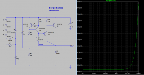
The first picture is the simplified circuit, and the second the full circuit without the pré-regulator, that is based on a lm317/337. The load current is 50mA
Today I was testing my shunt regulator that has a Pré-regulator, and I realize (remember) that when one use a pré-regulator there is no need for a great PSRR as the total PSRR is the sum of the pré-reg PSRR and the main-reg PSRR.
And, I want to design a new regulator for my headphones amplifier, that works in class A and consumes 50mA per channel.
So, I went to ltspice, and try to improve the output impedance of the Keantoken multiplier.
This is what I have right now. It uses the FdW current source. the bc337 will be good for at least 100mA, as the voltage at collector-emitter of Q1 is only 2 volts.
Q1 ,Q2 and R1 can be substituted by a Darlington. Diode D4 serves to fast charge the capacitor C2. I tried not to use exotic/hard to find componentes.
Improvement proposals are wellcome.
The first picture is the simplified circuit, and the second the full circuit without the pré-regulator, that is based on a lm317/337. The load current is 50mA
Attachments
Dan, it sounds like you're asking for a special kind of opamp. The thing is, low treble distortion tends to mean conditional stability into capacitive loads, hence necessitating an L/R at the output. For this reason an opamp that could work both as a reg and as a preamp would require careful design. But it is an intriguing challenge. You could ask the guys here about it:
http://www.diyaudio.com/forums/analog-line-level/218373-discrete-opamp-open-design-59.html
For a rail splitter, I would use an opamp and filter it's supply pins to improve PSRR. I was going to say that opamps have worse PSRR than chip regs, but then I realized I'm not really sure about that... Maybe certain opamps would be an advantage if used as regulators, owing to their speed?
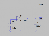
You can put a large capacitor in the output of a opamp , larger than 100uf. If the capacitor is too small or low esr the opamp can oscillate..
The ess reference DAC board has regulators based on this, I have tested with opa2134 and works good.
normally opamps have better PSRR than reg chips , new designs have better than 120db.
Attachments
You can put a large capacitor in the output of a opamp , larger than 100uf. If the capacitor is too small or low esr the opamp can oscillate..
The ess reference DAC board has regulators based on this, I have tested with opa2134 and works good.
normally opamps have better PSRR than reg chips , new designs have better than 120db.
Like here http://www.diyaudio.com/forums/anal...t-all-dc-coupled-riaa-preamp.html#post2162960
4th circuit 'CleanPos/CleanNeg'
Today I was testing my shunt regulator that has a Pré-regulator, and I realize (remember) that when one use a pré-regulator there is no need for a great PSRR as the total PSRR is the sum of the pré-reg PSRR and the main-reg PSRR.
And, I want to design a new regulator for my headphones amplifier, that works in class A and consumes 50mA per channel.
So, I went to ltspice, and try to improve the output impedance of the Keantoken multiplier.
This is what I have right now. It uses the FdW current source. the bc337 will be good for at least 100mA, as the voltage at collector-emitter of Q1 is only 2 volts.
Q1 ,Q2 and R1 can be substituted by a Darlington. Diode D4 serves to fast charge the capacitor C2. I tried not to use exotic/hard to find componentes.
Improvement proposals are wellcome.
The first picture is the simplified circuit, and the second the full circuit without the pré-regulator, that is based on a lm317/337. The load current is 50mA
Lower R1 (50...100 ohm) and add a base-stopper to Q1
") I think
I think 800uOhm at 100Khz looks very good.
Like here http://www.diyaudio.com/forums/anal...t-all-dc-coupled-riaa-preamp.html#post2162960
4th circuit 'CleanPos/CleanNeg'
Interesting. Did you not experience oscillations with only 1uF ? It seems a low value to me, the higher the capacitance the better, also a low ESR capacitor can make the open loop phase margin decrease enought to cause the opamp to start oscillating.
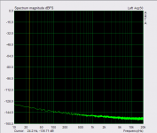
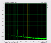
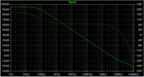
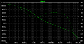
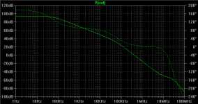
pictures from a opamp open loop gain and phase margin.
1 - without capacitor at the output.
2 - with 1000uf / 0.02 ESR (the phase degrades at 2 Khz where the output impedance is lower, more stable this way)
3 - with 1uf / 0.02 (phase margin is only 6º and the phase degrades at much higher frequency)
Attachments
Lower R1 (50...100 ohm) and add a base-stopper to Q1
800uOhm at 100Khz looks very good.
Thanks Frans, it seems that lowering R1 value will lower the loop gain. But I will try .
One thing that I have doubts is in the protection diodes, for take care of turn on and turn off , hoping that you and the rest of the guys could help on this matter.
it seems that lowering R1 value will lower the loop gain. But I will try.
And with that the possibility of oscillations
(and resent experience shows that a circuit like this can oscillate very easily ).Interesting. Did you not experience oscillations with only 1uF?
No, there have three builds of the preamp two by me and one by bksabath, none did oscillate
http://www.diyaudio.com/forums/anal...ll-dc-coupled-riaa-preamp-15.html#post3219427Yes, we are working on cap multipliers for an MC pre-pre stage.
Even rather simple implementations can be troublesome in this application.
Maybe in some hours i know more.
Working the cap multipliers do, no question, but wide bandwidth and low output impedance has to be considered in context. Then a quite simple circuit is a challenge.
Even rather simple implementations can be troublesome in this application.
Maybe in some hours i know more.
Working the cap multipliers do, no question, but wide bandwidth and low output impedance has to be considered in context. Then a quite simple circuit is a challenge.
No, there have three builds of the preamp two by me and one by bksabath, none did oscillate
My advice is to increase the cap value, and use a electrolytic with not to low ESR. Of course it is better to evaluate in breadboard, try different values.