He seems to have replace the attached circuit with a block diagram in later (?) descriptions
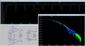
Ok, I gave it a try. Attached you will find my circuit and some results. The voltage sources where adjusted to give exactly the same output voltage for the enhanced and the standard circuit. The standard circuit uses exactly the same amount of microfarads as the enhanced version (both 10 mF).
The resulting graph for voltage and current flow shows one nice effect, the current into R7 is more constant and shows smaller loading peaks (5 A for the enhanced and 10 A for the standard circuit).
The FFT shows a 6 dB improvement, but above 360 KHz it is deteriorating.
When you measure the loading peaks supplied from the transformer you will see that these are almost equal for both circuits (the peaks for the enhanced circuit are a bit wider).
Overall, I do not think that this circuit is a major improvement over the standard circuit. It is a minor improvement for sure, but I do not think that it is worth the effort. Real life experiments must be done to get to a final conclusion.
Attachments
Thank you Frans. I expected no miracle but it seems to work fair enough. Something more to try. Have not seen it before.
You are right, Joachim,
but I think the first picture says it all. The purpose is to taylor a rectifier diode for a desired u/i curve. Gives nice soft overall switching.
but I think the first picture says it all. The purpose is to taylor a rectifier diode for a desired u/i curve. Gives nice soft overall switching.
You are working on the regulators that are already on Heseners board. Fine, we can use that for other projects. What we need is the components that go in the external box, Frans post 4336. That is what i call the pre regulator. For double mono we need two.
Tanks Joachim got it now.
Here is another circuit that claims less rectifier noise :https://picasaweb.google.com/lh/photo/rOgiSl8IVgPdqOcKLPkbNNMTjNZETYmyPJy0liipFm0?feat=directlink
More raw/pre power stuff
Ladies and gentleman,
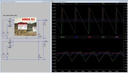
Today I invented a new component, it has 3 legs (in, out, ground), and it is called ‘Area 51’. 😱
Have a good look at the graphs, the upper one is of the standard circuit (the lower one) and the lower one (set of graphs) is of the ‘Area 51’ (upper) circuit.
See that the ‘Area 51’ component improves all specifications of the standard product (at an estimated cost of less than 3 Euro’s).
The output ripple is less than half
The transformer peak current is down from 10A to less than 2A
The capacitor charge current is down to less than 2A
The capacitor is charged during (about) 70% of the cycle.
Is this what you are looking for (stepped rectifiers, charge transfer power supplies end more).
Let me know (in the end I will reveal the contents of the ‘Area 51’ circuit. 🙂
Regards,
Frans.
Ladies and gentleman,
Today I invented a new component, it has 3 legs (in, out, ground), and it is called ‘Area 51’. 😱
Have a good look at the graphs, the upper one is of the standard circuit (the lower one) and the lower one (set of graphs) is of the ‘Area 51’ (upper) circuit.
See that the ‘Area 51’ component improves all specifications of the standard product (at an estimated cost of less than 3 Euro’s).
The output ripple is less than half
The transformer peak current is down from 10A to less than 2A
The capacitor charge current is down to less than 2A
The capacitor is charged during (about) 70% of the cycle.
Is this what you are looking for (stepped rectifiers, charge transfer power supplies end more).
Let me know (in the end I will reveal the contents of the ‘Area 51’ circuit. 🙂
Regards,
Frans.
Attachments
Ok I am quite curious... what should be this schematic ?
Not so quick, what do you think of it? What is your gestimate of the contents? Would you use it? etc... let me know and lets talk about it a bit 🙂
Regards,
Frans.
Most importantly, I would like to know how this compares with other circuits like the stepped rectifiers and the charge transfer supply. And I would like to know why you lot seem to like these (because I think the difference would be marginal).
Maybe the question is; go on convince me, teach me some 'high end' voodoo. You see I am a bit of a skeptic (about those tweeks) 🙂
Maybe the question is; go on convince me, teach me some 'high end' voodoo. You see I am a bit of a skeptic (about those tweeks) 🙂
I am not an expert circuit analist... I mainly judge the results by what I can hear... so I must build it and listen before I can post any opinion.
(The truth is: I do not completey understand the graphs you posted)
(The truth is: I do not completey understand the graphs you posted)
I am not an expert circuit analist... I mainly judge the results by what I can hear... so I must build it and listen before I can post any opinion.
(The truth is: I do not completey understand the graphs you posted)
The graphs mostly show the currents that flow in the circuit.
More precise, the currents delivered by the voltage source (transformer) these are I(V1), I(V2), I(V3) and I(V4) and they are 11A, 11A, 2A and 2A.
The next one is the charging currents of the capacitors I(C1) and I(C2) and they are 10A and 1A.
The load currents I(R3) and I(R5) both at 1A
The load voltage V(V+a) and V(V+b), these are 'Area 51' and 'standard' circuit, both about 14V but the 'Area 51' circuit gives half the ripple voltage.
Regards,
Frans.
I would not use a chopper Opamp for servo.
Frans, so far i have no idea. Does the circuit have any voltage drop ?
Frans, so far i have no idea. Does the circuit have any voltage drop ?