Well, the GND layout is the same as before and I did not have any hum with the v1.
With the v12 fullfilm I hear a slight hum when at full power and no signal in.
I guess the big caps are picking up from the nearby psu lines.
I believe it is a field because the hum is greatly reduced just by closing the riaa case lid")
But the very V1 layout on its own board maybe had some tighter ground? But the lid surely is a strong sign you got to shield first.
Joao, What variant of the sk170 are you using? GR= 3-7 BL = 6-12, and V= 10-?. I was curios, if I could find the V variant it may eliminate the need for a buffer all together and still have a reasoably low impedance.
Don't eliminate the output buffer. Then your Zo will be second stage's load resistor no matter the current in that stage.
I wonder if this is telling you that a flow and return of a circuit are separated creating a large loop area. That loop area then picks up the field and generates a voltage that you hear as hum.I believe it is a field because the hum is greatly reduced just by closing the riaa case lid
LOOP AREA is critical in attenuating interference, both at source and at receiver.
the circuit supplying power to your active amplifier arrives via two wires (dual polarity requires three wires).
The current from the PSU flows through one wire and returns via the other wire. That is what makes it a circuit, a circular route.
If the flow and return wires are separated then the loop area acts as a transmitting aerial sending interference out for any other circuit to pick up.
Minimise the transmitting loop area by keeping the circuit short helps, but this cannot be made infinitely short.
Twisting the two flow and return wires together has the effect of canceling the transmitted field for all other circuits that are a significant distance away, compared to the gap across the twisted pair.
A similar aerial effect occurs with input circuits. The Flow and Return must be closely coupled and preferably short to minimise the loop area between the wires forming the circuit. A bigger loop area will act as a more effective receiver aerial.
All electronics depends on circuits.They all have a flow and return route. The current must return to it's source, otherwise it is not a circuit. The layout design for all electronics should take account of the flow and return routes for effective interference attenuation and also for parasitic effect attenuation.
It is very possible that your V1.0 and V1.2 layouts (both PCB traces and external wiring) were implemented quite differently. If V1.0 performed well you need to replicate what was good about it's layout when implementing V1.2
LOOP AREA is critical.
Last edited:
I was going to eliminate the buffer. Would have to find a V variant first, which is like trying to find a Hens tooth.
The only thing that a V will do is that it can run more current so to make the 2nd stage's drain load resistor smaller for same gain given the same B+. Still it will be kOhm. Without a buffer its too much. Done that, the buffer plays better. That is why there is buffer in Franz's although he used V all over.
I need to read my posts better. That was suppose to say "I wasn't going to eliminate the buffer".
Because you are a tube guy it rung true. Tube guys avoid buffers because many have negative experiences by using the wrong tube. They do the paper highs stiff mids thing. This buffer in your design can pass 200kHz square, another story. My 6V6 trioded configured as a 30mA bootstrapped cathode follower is doing the dynamics and tone thing significantly better than my DCB1 no matter the two needed Teflon caps, and that is what I use my simplistic with.
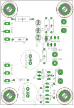
Ok. Here is my latest shunt layout with suggested changes included. Went back to single brd per shunt to allow better distribution on heat sinks and to improve chassis layout. Would this circuit benefit with a top plane of copper grounded to chassis?
Gate stoppers on Fets.
Grounds brought to center of board in large copper pad.
It worked out that sense components are isolated from power side.
Anything glaringly wrong?
Gate stoppers on Fets.
Grounds brought to center of board in large copper pad.
It worked out that sense components are isolated from power side.
Anything glaringly wrong?
Attachments
Looks well distributed. Just check that all connections are 100% compliant with your reg schematic for one last time. I don't think that a top ground plane will add anything more than unwanted capacitance. When you will finish it, just connect a dummy load for say 40mA consumption with all 4 wires (twisted per force and sense pairs) and connect the oscope across that load and sweep time and voltage knobs. You got a fine HP oscope recently when debugging your valve amp I remember. If it gives you a thin straight line, you are done.
P.S. Don't forget to mini sink the BC546 that has the Jfet collector load.
P.S. Don't forget to mini sink the BC546 that has the Jfet collector load.
Joao, What variant of the sk170 are you using? GR= 3-7 BL = 6-12, and V= 10-?. I was curios, if I could find the V variant it may eliminate the need for a buffer all together and still have a reasoably low impedance.
SG
I use a BL version. Maybe you can use a V variant, but my way is to work with transformers, as well I like to have stable impedance standards: the studio norm 600 ohm output impedance and 10Kohm input impedance.
Other point is to drive cables at the output easely so I like to use medium power transistor on the output stages. My experiences with driving the LCR RIAA showed me that's better to drive them with more ability in delivering current.
Here is what I was commenting. I thought you said using a buffer after first stage too.
That would be a nice idea to use a buffer after every stage to drive ...
A buffer although sometimes beneficial, I use it in the simplistic too, its a stage on its own utilizing 100% local feedback in my eyes. Zo with the Jfet buffer here is around 40 Ohm. Else my DCB1 unity pre isn't a stage, its a glowing wire for connecting people's CDPs.
What's DCB1 and with which JFET you get the 40 ohms?
Of course you have 100% feedback, but local feedback. Remember in triode, which so many music lovers prefer, you have local feedback as well because of it's internal electrical structure!
I agree that you can use paralleled FET / BJT for getting more current, and then dynamic, but see my response to SGregory because I like the idea of using a buffer.
Another topic regarding your answer with BJT as input device of the phono stage. How would you solve the problem with tha base voltage - I mean that the base voltage is 0V - and not using an input capacitor?
DCB1.
Short answer for 0V in a BJT headamp is...never. Complementary symmetrical beta matched emitter follower input with trimmed current source can go a long way though. Still, in case of failure, happens to carts what happens to speakers if a complementary amp fails.
This is a wide discussion about general electronics ideas for phono non the less, and not about a certain concept that the simplistic is...
DCB1.
Short answer for 0V in a BJT headamp is...never. Complementary symmetrical beta matched emitter follower input with trimmed current source can go a long way though. Still, in case of failure, happens to carts what happens to speakers if a complementary amp fails.
This is a wide discussion about general electronics ideas for phono non the less, and not about a certain concept that the simplistic is...
Thanks for the explanation! May I have one other question - not direct related with the RIAA amp
I exoerimented with the SK170 in a linestage as well but I think this is not the best device for this application. Any suggetion what transistor is better suited for a line stage?
Last edited:
LOOP AREA is critical.
I just replaced power lines from psu to shunts with coax mic cable and did the same in the sense wires from shunt to riaa (another type of coax).
Things got better but I still hear hum at full power and if I remove the lid, hum is all over the place.
I am sure there is no ground loop (as it would be aparent even with the v1 shunts)
I am inclined to the Loop Area idea. What can we do in a pcb to reduce it´s antena effect ?
I can modify the layout so Force runs near GND lines inside the pcb area but can it help ?
Ricardo
The lid thing says it must mainly be loop area pick up. It would be great if you could see with an oscope that your power lines are free of any oscillation too. Can you shield the force cable runs also?
By tightening and shortening the gnd runs near power runs everywhere is certainly beneficial. Also, can your big film psu caps change orientation for a test, or just move regs in angles a bit and see if something changes?
By tightening and shortening the gnd runs near power runs everywhere is certainly beneficial. Also, can your big film psu caps change orientation for a test, or just move regs in angles a bit and see if something changes?
- Home
- Source & Line
- Analogue Source
- Simplistic NJFET RIAA