@myleftear
-Input stage TP voltage drift cycle is normal especially when unboxed at highest gain. Nonetheless it should not usually exceed +/- 2V over 30 minutes in a stable room temperature. Unless there is airconditioning or other air drafts going on. If you alternatively set for 40dB it should stabilize due to higher source resistance and that's also a normality check.
-Your new Q4 Q5 Q6 DC bias measurements look healthy.
-Measuring at the input RCA you should read chosen Rx. Probes polarity can play a role on a direct JFET input with some DMM. Try them both ways. At the output RCA you should read about 1 MegOhm. Very different results are suspect.
Hi,Hello,
I'm just starting to build this preamp with a TeaBag kit. I've only populated the shunt reg part and I already have an problem.
With a 12v to 50v input, I have a 3.5v fixed output voltage. I don't talk about TP but 'PSU OUT' with 2k2 load.
For example, with a 40v input, the IRF9610 have 36V at the gate and 3.5V output. Is there a part that seems to be failing ? (what should I test first ?)
I have checked components values.
To make things easier , I cannot compare voltage with the other channel because I have the same problem on both
Did Imissed something in my test ?
-First check the voltage drop across R1's legs to see if there is healthy CCS bias in the reg sections. Normal reading should be 0.57-0.6V. That indicates about 100mA constant current presence for a 5.6R R1. 2k2 dummy should only consume 15.45mA at 34V output thus its not a wrong value test load for this application. Also verify R1's Ohmic value when the power is off.
-Verify that Q2,Q3 are the right PNP type transistors first. Then when the power is off, test their collector to base and base to emitter junctions. An on board easy way for doing that is set DMM in diode mode, put the black probe on base pin and keep it there. Try the collector and base pins with the red probe. For good transistors each junction should show 0.5-0.7V with Vbe reading slightly higher than Vcb. This test is valid for all PNP transistors in the circuit. Not for JFETs though.
-M1 and M2 Mosfets when normally conducting should read 3-4V between their gate and source pins 1 and 3.
Just measured the connectors, the muted channel has incorrect values, so I cut them off. (It is still muted  )
)
Redid the output connection, measures 1m now...
Will do the input tomorrow, whith a little luck I'll have it fixed with that.
This remninded me something I was repeatedly struggling with: The shield of a coax is "usually" being used as ground, but it's always much too much copper to properly fit the connector. How are others come along this?
)Redid the output connection, measures 1m now...
Will do the input tomorrow, whith a little luck I'll have it fixed with that.
This remninded me something I was repeatedly struggling with: The shield of a coax is "usually" being used as ground, but it's always much too much copper to properly fit the connector. How are others come along this?
Goode evening Salas
I haven’t had success yet, one channel ist still muted.
Measured all Q1 - Q6 on both channel, drain to ground, , they're in the same ballpark of 7.6V - 7.8V, and Q6 19.9V. Both channel measure very much the same. (I haven't the precise numbers with me)
I went ahead and redid all sockets. They now seem fine: 100 Ohm input resistance, 1 mOhm output resistance... that pesky channel is still muted (not totally, just attenuated a lot). I will try to search for a short, solder-blob or anything like that on the "bad" board. Do I have other options?
Thank you!
I haven’t had success yet, one channel ist still muted.
Measured all Q1 - Q6 on both channel, drain to ground,
, they're in the same ballpark of 7.6V - 7.8V, and Q6 19.9V. Both channel measure very much the same. (I haven't the precise numbers with me)I went ahead and redid all sockets. They now seem fine: 100 Ohm input resistance, 1 mOhm output resistance... that pesky channel is still muted (not totally, just attenuated a lot). I will try to search for a short, solder-blob or anything like that on the "bad" board. Do I have other options?
Thank you!
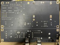
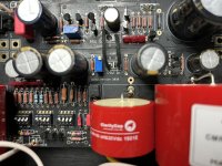
thank you, Rick!Post some good pictures of front and back, more eyes, more likely to find something.
I‘ll need a few days to get back to it, things are turning crazy here 😓
-Check if the DIP switches give continuity to the right bias resistors for the gain mode you had chosen. Can it be a mistake in values between channels?Do I have other options?
Thank you!
-Make sure TP DCV reading is in ballpark for the almost mute channel before disassembly. Because if too high or too low it bottlenecks the input stage.
I checked the boards for any misplaced resistor, by tea-bag's schematic and pcb-picture (to determine the positions on board) they're where they have to be. Measurements confirmed this.
I checked the dip-switches S1-S4 one by one, but not the rest, will do this tomorrow.
My oh my... I'm getting convinced there's a solder-blob or something stupid like that, as the jfets seem well and boards are built equally (checked twice, but never say never).
A propos transistors: Q3 measured a steadily sinking voltage, from 6V (a few minutes after powering-on UFSP) down to 5.3 some minutes later... I didn't let it on much longer. Is this in correlation with the TP voltage drift I guess?
And by the way, here's the whole Q1 - Q6 measurements, both channels:
* left (bad) | right (good)
Q1 7.90 | 7.90
Q2 7.91 | 7.90
Q3 6 - 5.3 | x - 5.3
Q4 7.92 | 7.69
Q5 7.91 | 7.67
Q6 19.0 | 19.02
Next thing: examine dip-switches S5 - S12, then soldering, then... we shall see!
It is still fun, sort of!
another aerobatic measurement. Q3 pin 3 to ground = 7.92V, Vbe 0.78V
the dip-switches seem ok, they close and open independently on switching. Controlling continuity to their resistors seems difficult as a closed switch seems to be measurable all the way through all resistors in the „network“…
the dip-switches seem ok, they close and open independently on switching. Controlling continuity to their resistors seems difficult as a closed switch seems to be measurable all the way through all resistors in the „network“…
Pin3 on a BC327 (Q3) is emitter and 7.92V is very close to what is expected. The same voltage should be found on the drains of Q1 & Q2. The four LEDs Vref seems like biasing the 327's base pin2 at about 7V. Is it so? On collector pin1 we get the test point (TP) voltage which should be around 4V after adjustment. If those conditions are met the input stage is working as it should. Are there about 40mV across the pins of R2 and R3 for each one so we know S5 & S6 are correctly engaging and you don't run on one cylinder? That both Q1 & Q2 provide current I mean. Do you use comparable Rail voltage on both channels?
Uhm…
It is embarassing… but good news: UFSP IS FINE!
I removed the boards and the inpuf- and output-wires weren’t soldered very well. Reflowed them and put the boards back, and plugged them in. Still one channel missing, and all of a sudden I tried the other input on the preamp. Bam, wonderful stereo!
So I have to re—think my logic and fix that DCG3, if at all, as both channels (Phono + computer) are playing fine. Whatever it was!
Hahaha.
Attachments
Last edited:
Good evening Salas and friends!
Now that it is going, I am finally enjoying playing records. It is great, because it is wonderfully clear and vivid! I can't comment on stage depth etc. due to bad speaker positioning, but so far it is just plain cool!
(I'm running a TD-125 with SME 3009 s2 imp and AT 33 PTG 2, into UFSP, into DCG3, into ZM Old Soul, into KEF 101/2 ...)
The installation is far from ideal, crammed into a tiny corner of my atelier because I still am waiting for the front room to be handed over. There they'll stay!
Salas, your guidance was absolutely helpful, I would have been so lost without it...
There's one last issue though: When I turn on UFSP, I have a hum, out of the speakers. it is of constant volume (doesn't get louder when I increase volume). It sounds a bit like a typical transformer-hum... Can that be a ground-loop of sorts? I wired the 2 boxes as per your build-guide...
Salas is the authority here of course—but I did have a fast instinctual thought—how is your tonearm grounded? Post insulated or not? This really mattered in both FSP and Ultra builds (insulated post in both builds, hum when connected to chassis)—doesn't matter at all in this most recent pre I made, go figure—I'm sure it's my lack of understanding. Congrats!
- Home
- Source & Line
- Analogue Source
- Simplistic NJFET RIAA