
How can I use two raw PSU, one internal (...) and one external (...)?
Use a toggle switch. DPDT On-On.
The switch is only for the L and R positive rails and not GNDs, correct?
Yes switch only the L&R positives.
Now that I am at the PCB/wiring layout stage I have realised that if I do not switch the GND when I use the external PSU, the preamp chassis will still be linked to the GND through the 10R of the unused internal RAW PSU. Is this what I want?
If there will be no ground loop buzz noise, its better everything chassis to be on the same reference. But the 10R is a breaker and it should help avoiding a loop. Its a practical thing you will see in test. If you will definitely need a double switch or not.
How you established its fine? You measured Ω across the cartridge's output pins?
Thank you, Salas.
As I stated, I am prone to glitches. The cartridge is fine, I have a channel-issue in UFSP: left channel is a lot more quiet than the right one. Hope it’s just the gain-switch… unfortunately I can‘t dive into it right now, as I must work.
Good evening Salas!
Yes, I went the easy(-est) way: measured Ω across the cartridge's output pins, with a 100r inbetween. Measured as quick as I could, 0.5 - 1 second maybe... (I guess that's naive as the thin wire would've melted already") ) Both channels showed 109r + something.
) Both channels showed 109r + something.
Then I connected one channel only, to UFSP left = low gain, then right = normal gain.
Then the same with second channel, to UFSP left = low gain, then right = normal gain.
The result was left UFSP channel's output gives much lower output, consistently with both Cartridge-channels, so that seems pretty clear doesn't it?
Yes, I went the easy(-est) way: measured Ω across the cartridge's output pins, with a 100r inbetween. Measured as quick as I could, 0.5 - 1 second maybe... (I guess that's naive as the thin wire would've melted already
) Both channels showed 109r + something.Then I connected one channel only, to UFSP left = low gain, then right = normal gain.
Then the same with second channel, to UFSP left = low gain, then right = normal gain.
The result was left UFSP channel's output gives much lower output, consistently with both Cartridge-channels, so that seems pretty clear doesn't it?
Good evening Salas!
As I found a spare 45 min, I dipped my toe into the debugging procedure. Not sure about the best strategy though, so I decided to start with the simple stuff. Compared the board's population, all seems good. (I am confident solder joints are good too, for now)
Controlled the dip-switches settings, they are good. (Set for a loMC)
Next, control wiring. Input connectors seem good, output connector is funny:
Good channel measures 0.2r hot / ground, shorting both returns jumpy megaohms.
Bad channel measures 0.2r hot / ground, shorting both returns ... 3r.
I guess this is the bugger?
Thanks already
david
Gotta go home, today is wedding-day #14 ...
I'll probably get back on it tomorrow, for another hour
Ok, thank you, and good morning, Salas!
[jedi self-hypnotize mode on]
I will go the route you tell me.
I will find the error by that route
[jedi self-hypnotize mode off]
I hope you don’t mind the little self-ironic joke above, just have to make a bit fun of the situation.
You always foresaw the problems spot-on, so there’s just my lack of knowledge in the way…
Thank you again for project and guidance!
Your measurements are weird. Drain to ground (PSU 0/chassis) for Q4 should be 7-10V and about the same as Q5's drain to ground. Q6's in the vicinity of 20V. I suspect dead Q5. With power off measure RDS Ohm across Q5's drain to source pins (1 to 3). If a short or OL its bad news. Normal is 30-40 Ohm RDS for a K170 BL.
Thank you.
I thought they weren't proper.
I measured drain to ground, (input G)...
I was a bit in a rush and did not make experiments like using other Gnd, or measuring from the other outer leg (source)...
There's one hope that I made a mistake and it's not a dead bug: The working channel measured the same... ?
Attachments
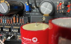
Salas,
Thank you very much! The coax looks fine (at the input), it’s view-angle and focus.
BUT on this side, I have contiinuity between hot and shield/gnd on both in + out… I suspect (hope!) this is the glitch.
This time the measurement seem to fit:
Pos | bad | good
——————————
Q4. | 7.76 | 7.87
Q5. | 7.82 | 7.89
Q6. | 19.08 | 19.98
Another thing I observed: the bias. I readjusted it to 4V the day before, after ufsp was on for around 20 min, I constantly and slowly went down and I upped it to 4V seceral times.
When I measured again, after ~15 min, it was at 5.6 slowly going down. Is this normal behaviour?
Have a good day!
Hello,
I'm just starting to build this preamp with a TeaBag kit. I've only populated the shunt reg part and I already have an problem.
With a 12v to 50v input, I have a 3.5v fixed output voltage. I don't talk about TP but 'PSU OUT' with 2k2 load.
For example, with a 40v input, the IRF9610 have 36V at the gate and 3.5V output. Is there a part that seems to be failing ? (what should I test first ?)
I have checked components values.
To make things easier , I cannot compare voltage with the other channel because I have the same problem on both
Did Imissed something in my test ?
- Home
- Source & Line
- Analogue Source
- Simplistic NJFET RIAA