Powerline(reduced) magnetic HFI coupling, & EFI/PSl/GPI aggressors
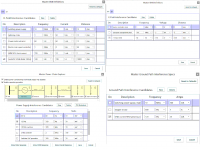
Following up on the PowerLine magnetic interference, I activated all FOUR interference databases [shown in Attachment#1] and edited Electric and GND databases to add phono-preamp-specific interferers. To respect the RIAA thread's attention to power-supply-ripple, I edited the PowerSupply LRCRCCC network to use 100_ohm and 10,000UF RC followed by 100_ohm and 100uF. Turns out the Ground_plane interference is TOO BIG leave on, since 25mA 120Hz ripple returning thru 21milliOhm of cable from MovingCoil to Shunt/first2SK170, scaled by gain of 78dB, is over a volt of 120Hz. This produced a -5dB SNR. So I de-selected the GPI gargoyle [ see far right of Attachment#2---GPI is off].
With just Magnetic and Electric and PowerSupply aggressors, we drop from 73dB (JohnsonNoise only) to 62.6dB.
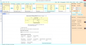
Attachment#2 shows the status of InterStage wiring: we have 1meter TwistedPair now; and 14mm PCB trace from Shunt to firstgainstage, and 14mm PCB trace from firstgainstage to Rseries that feeds the RIAA. Please note the 4th stage Interconnect (and those on down) have been disabled.
I pick up 26dB using TwistedPair; I edited the HFI database to move the aggressor wire 100X further away, from 100mm to 10,000mm; this simulates the use of parallel-hot-rtn power cabling inside the wall and that this cable is randomly twisting and thus not optimally coupling into our cartridge-to-Preamp cable. The HFI-injected interferer dropped from 0.1dB SNR [refer to prior post] to ~68dB.
Attachment#3 provides stage-by-stage AnalysisDetails [ referred to OUTPUT of Signal Chain] for each of HFI/EFI/PSI/GPI.
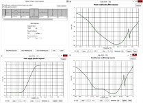
Attachment#4 introduces the available VDD filtering; I made the first cap be 10,000uF; resistor to left is 100_ohms, thus a 1 second tau and F3dB of 0.16Hz. resistor to right is also 100_ohms but feeds 0.1uF and 100UF caps which improve ripple reduction only above 160Hz. Note the ugly resonance at high frequencies. I manipulated the PSRR (important for the 2 gain stages) to properly represent the 0DB PSRR of discrete drain-load stages; the 40dB PSRR plot (see Attachment#4) compensates the stage-gain of 40dB.
Questions?
Following up on the PowerLine magnetic interference, I activated all FOUR interference databases [shown in Attachment#1] and edited Electric and GND databases to add phono-preamp-specific interferers. To respect the RIAA thread's attention to power-supply-ripple, I edited the PowerSupply LRCRCCC network to use 100_ohm and 10,000UF RC followed by 100_ohm and 100uF. Turns out the Ground_plane interference is TOO BIG leave on, since 25mA 120Hz ripple returning thru 21milliOhm of cable from MovingCoil to Shunt/first2SK170, scaled by gain of 78dB, is over a volt of 120Hz. This produced a -5dB SNR. So I de-selected the GPI gargoyle [ see far right of Attachment#2---GPI is off].
With just Magnetic and Electric and PowerSupply aggressors, we drop from 73dB (JohnsonNoise only) to 62.6dB.
Attachment#2 shows the status of InterStage wiring: we have 1meter TwistedPair now; and 14mm PCB trace from Shunt to firstgainstage, and 14mm PCB trace from firstgainstage to Rseries that feeds the RIAA. Please note the 4th stage Interconnect (and those on down) have been disabled.
I pick up 26dB using TwistedPair; I edited the HFI database to move the aggressor wire 100X further away, from 100mm to 10,000mm; this simulates the use of parallel-hot-rtn power cabling inside the wall and that this cable is randomly twisting and thus not optimally coupling into our cartridge-to-Preamp cable. The HFI-injected interferer dropped from 0.1dB SNR [refer to prior post] to ~68dB.
Attachment#3 provides stage-by-stage AnalysisDetails [ referred to OUTPUT of Signal Chain] for each of HFI/EFI/PSI/GPI.
Attachment#4 introduces the available VDD filtering; I made the first cap be 10,000uF; resistor to left is 100_ohms, thus a 1 second tau and F3dB of 0.16Hz. resistor to right is also 100_ohms but feeds 0.1uF and 100UF caps which improve ripple reduction only above 160Hz. Note the ugly resonance at high frequencies. I manipulated the PSRR (important for the 2 gain stages) to properly represent the 0DB PSRR of discrete drain-load stages; the 40dB PSRR plot (see Attachment#4) compensates the stage-gain of 40dB.
Questions?
Attachments
Response to rick mcinnis: how DIYers use HFI/EFI/PSI/GPI predictions
Rick
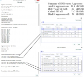
With our ears able to hear repetitive trash down to 4 parts per million (0.0004%, -105dB) or lower, these supposedly simple PreAmps / cables / power are extreme design challenges. Hence the interest in using SCE to understand and predict and suggest alternative physical arrangements. Make some area or distance alterations, click the "Update" button, and 1/3 second later you get a new estimate for the SNR.
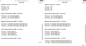
Consider the "both_Analysis", Attachment#3, right side text tables.
At the very top "Aggressor summary", with 1.14Voltsrms of trash/interferers/aggressor_output from the RIAA Preamp, we see the GPI level is 1.14Volts, nearly 3,000X the HFI magnetic and 25,000X the EFI electric coupling. So first, make sure both wires of Left and of Right channel [all 4 wires] from cartridge to Preamp are floating. Without that, and without attention to other return paths of the power-supply's full-wave rectifier return currents, the Preamp is unusable. Hence you builders locate the PowerSupply on a separate PCB, and often place the PowerSupply in a separate metal box with only a DC_powercable running between the two boxes. That....separation of all the 60&120Hz fields and currents....is key.
Next, we have HFI magnetic fields. USE TWISTED PAIR (maybe coax is even better). And keep the cartridge-preamp wiring away from power wiring, especially the 100watt Audio PA power cords. Orientation matters.
And distance. Don't bundle the signal cables up, neatly, with the power cords.
Then we have EFI electric fields. Even with 5_Ohm resistance of the MC cartridge[prior post], Efield coupling into the TwistedPair from 4" away results in 48uV out of the Preamp [ for Efields, the lower the resistance in that part of the circuit, the cleaner the circuit will be.] By the way, you can examine the SCE menus, and disable EFI into any chosen inter-stage wire.
The EFI database (part of attachment#1), which I edited ["new" button]
assumes you have a 117voltAC (170volt peak) 60Hz wire running only 4 inches away from all stages of the SignalChain. Turns out, for Electric fields in a non-ground-plane situation, it does no make much difference whether the Aggressor wire is 4" above or 4" off to the right of the 14mm(default).
Conclusion: keep the power wiring away from the TwistedPair input cable, and not inside the Preamp box.
But you know all this. SignalChainExplorer merely used 2_D and 3_D models of these interferers (very simple topologies) to predict the SNR, and surprise, what we are told...........is true.
More later.
tankcircuitnoise
Rick
With our ears able to hear repetitive trash down to 4 parts per million (0.0004%, -105dB) or lower, these supposedly simple PreAmps / cables / power are extreme design challenges. Hence the interest in using SCE to understand and predict and suggest alternative physical arrangements. Make some area or distance alterations, click the "Update" button, and 1/3 second later you get a new estimate for the SNR.
Consider the "both_Analysis", Attachment#3, right side text tables.
At the very top "Aggressor summary", with 1.14Voltsrms of trash/interferers/aggressor_output from the RIAA Preamp, we see the GPI level is 1.14Volts, nearly 3,000X the HFI magnetic and 25,000X the EFI electric coupling. So first, make sure both wires of Left and of Right channel [all 4 wires] from cartridge to Preamp are floating. Without that, and without attention to other return paths of the power-supply's full-wave rectifier return currents, the Preamp is unusable. Hence you builders locate the PowerSupply on a separate PCB, and often place the PowerSupply in a separate metal box with only a DC_powercable running between the two boxes. That....separation of all the 60&120Hz fields and currents....is key.
Next, we have HFI magnetic fields. USE TWISTED PAIR (maybe coax is even better). And keep the cartridge-preamp wiring away from power wiring, especially the 100watt Audio PA power cords. Orientation matters.
And distance. Don't bundle the signal cables up, neatly, with the power cords.
Then we have EFI electric fields. Even with 5_Ohm resistance of the MC cartridge[prior post], Efield coupling into the TwistedPair from 4" away results in 48uV out of the Preamp [ for Efields, the lower the resistance in that part of the circuit, the cleaner the circuit will be.] By the way, you can examine the SCE menus, and disable EFI into any chosen inter-stage wire.
The EFI database (part of attachment#1), which I edited ["new" button]
assumes you have a 117voltAC (170volt peak) 60Hz wire running only 4 inches away from all stages of the SignalChain. Turns out, for Electric fields in a non-ground-plane situation, it does no make much difference whether the Aggressor wire is 4" above or 4" off to the right of the 14mm(default).
Conclusion: keep the power wiring away from the TwistedPair input cable, and not inside the Preamp box.
But you know all this. SignalChainExplorer merely used 2_D and 3_D models of these interferers (very simple topologies) to predict the SNR, and surprise, what we are told...........is true.
More later.
tankcircuitnoise
TCN,
I do look forward to hearing more.
What I read into it before your clarification (thanks for that) was that "this is what we do", maybe not to perfection though I know there are many who will experiment with the placement of components using a 'scope probe to know where the "quietest" spots are. Only recently getting a 'scope I had hoped that this was not all that necessary. Your report has changed my mind. AS you found there is a real reason for all of this.
I am in the process of remaking my SALAS raw power supply and have been inspired to at least attempt to see how much difference orientation of my chokes and transformer will make, I had used the traditional 90 degrees to each other but I might have all of this too close together. The raw supply is a minimum of two feet away from the PCB. I use twisted pairs of likely too large a gauge for the umbilical. Maybe I should try some good co-ax for these? I need to change my routing, too, with the hopes of improvement.
Take care,
How to acquire a copy of "Signal Chain Explorer"
Having reread "The Rules" of diyAudio just now, I'll simply mention the website
robustcircuitdesign.com
There are download buttons, from what I remember.
You'll get a moderate size executable [ 10 or 20 Megabytes ] and then should you not already have Microsoft .NET installed, the .NET libraries also get downloaded.
SCE opens with 2 stages by default
1) voltage-sensor with 1milliVoltpp
2) 12-bit ADC
Click on the far right "Update" and you'll see SNR and ENOB values.
Click "Bode Chart" and you'll see Frequency response: magnitude/phase.
You can freeze these charts, and annote the title as you wish.
Click "Analysis Details" and the contributors to the signal errors are listed in a text document.
Click on "Gargoyles", also enabling one or more of HFI/EFI/PSI/GPI, and click "Update" once again, and the SNR should collapse and ENOB may go to zero. You already know you can edit the databases: click on EFI button.
Again click "Analysis Details" to see many more contributors to the signal errors. All this with just two stages.
In topright, enable "Parasitics" and the bondwires and ESD diodes come into play; alter the Bode StopFreq to 100GigaHertz and you'll see bumps and dips at high frequencies.
In topright, enable "I/C" and the default 14mm PCB trace is added. You
don't be advised of that presence unless you look on topleft and click "Show Interconnects". Update the Bode, probably seeing a bump/peak near a GigaHertz.
Edit the Sensor stage resistor value to be 100,000 Ohms and see the SNR degrade. Maybe turn off the Gargoyles.
You edit the ADC properties in both the topleft Settings / Sampling worksheet and in the worksheet that appears when you on the ADC stage rectangle.
To delete or move stages, use the RightMouse button.
Now, if you could just insert OpAmps or discrete Rs & Cs and Ls and compensation networks, and single transistors. Oh, you can.
tankcircuitnoise
Building Salas circuit in Signal Chain Explorer
To produce a clean signal with 106dB SNR and 250uVpp cartridge output, the aggressors need to be 1/200,000 of the signal or 1.25 nanoVolts referred to input.
Here is how to build the Salas circuit in Signal Chain Explorer.
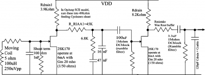
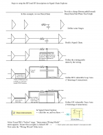
Attachment#1 shows the circuit; we'll use fast-but-imprecise opamp models for the 2SK170 devices. Once you've build the signal chain, you can experiment with different aggressors (interferers) at different distances, or frequencies (400Hz aerospace ripple ), and different sources (switch regs).
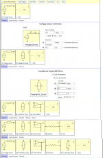
Attachment#2 shows the signal chain being build from left to right. You pick the type of stage in the left-margin tabs, hover the mouse over your choice of stage, and DOUBLECLICK. As you insert a stage, you can edit the R&C values then, or come back later; just click on a stage to edit values.
To get more display room for the signal chain, find and click on the topleft
"<" and ">".
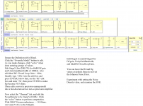
Attachment#3 shows completion of the full signal chain. Notice I added a cap at the very end, to represent an output LowPassFilter to control Johnson noise. I also deleted the 50_ohm resistor (intended to be Rout of a Source Follower buffer, but definitely a modeling error, so I deleted it).
Text at bottom at Attch#3 guides you to implement the 2SK170 models.
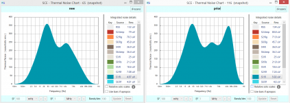
Attachment#4 shows some possible detective work. I had an error in building this new signal chain, the error showing up in slightly different
SNR. So I exploited a feature of the ThermalNoise plot, to view ONE of the very small noise sources, magnified. The error was "wrong UGBW for the first gain stage". A typo.
Now, with your own private copy of the RIAA preamp, you can tinker with various HFI/EFI/PSI/GPI aggressors.
To produce a clean signal with 106dB SNR and 250uVpp cartridge output, the aggressors need to be 1/200,000 of the signal or 1.25 nanoVolts referred to input.
Here is how to build the Salas circuit in Signal Chain Explorer.
Attachment#1 shows the circuit; we'll use fast-but-imprecise opamp models for the 2SK170 devices. Once you've build the signal chain, you can experiment with different aggressors (interferers) at different distances, or frequencies (400Hz aerospace ripple ), and different sources (switch regs).
Attachment#2 shows the signal chain being build from left to right. You pick the type of stage in the left-margin tabs, hover the mouse over your choice of stage, and DOUBLECLICK. As you insert a stage, you can edit the R&C values then, or come back later; just click on a stage to edit values.
To get more display room for the signal chain, find and click on the topleft
"<" and ">".
Attachment#3 shows completion of the full signal chain. Notice I added a cap at the very end, to represent an output LowPassFilter to control Johnson noise. I also deleted the 50_ohm resistor (intended to be Rout of a Source Follower buffer, but definitely a modeling error, so I deleted it).
Text at bottom at Attch#3 guides you to implement the 2SK170 models.
Attachment#4 shows some possible detective work. I had an error in building this new signal chain, the error showing up in slightly different
SNR. So I exploited a feature of the ThermalNoise plot, to view ONE of the very small noise sources, magnified. The error was "wrong UGBW for the first gain stage". A typo.
Now, with your own private copy of the RIAA preamp, you can tinker with various HFI/EFI/PSI/GPI aggressors.
Attachments
Enable "I/C", to see HFI/EFI/GPI.
Those aggressors couple into the inter-stage mechanical structures, thus I/C must be enabled (on far right).
Interstage Mechanical Structures? A trace (defaulting to 14mm) above a return path provides the needed LOOP for magnetic field HFI aggression.
Length of trace, and Height above RTN, define the Area.
That same trace has length and width; the product of L * W is the area for electric field EFI aggression.
The return path, under the trace, running between stages, has resistance.
That resistance, times the Ground Current, is the GPI aggressor voltage.
Just finished my Simplistic Phono Preamp and I couldn't be more pleased. Magnificent piece of electronic design. Thank you Salas for this design and thank you Tea-Bag for the kit of boards and parts.
Setup was quite straightforward following the directions. Both channels had 32.5 volts for the 3.6 volts across TP1 to TP2, a bit lower than expected but not of concern.
Acid test: hooked up to the turn table and the preamp, turned up the volume to full it was difficult to discern a whisper, brilliant. Put on the first record, The Last Concert by the MJQ, a reasonable test for any system, and the result, glorious sound, clear, balanced, vibraharp sounding superb, every note on the bass clearly enunciated. Just magic.
Again, thanks. Pictures will follow when I figure out how.
Graeme
Computing HFI magnetic loop area, EFI electric wiring area for SCE
Whew. Lots of thinking of how to describe THE WIRING MODEL.
Between the stages of Signal Chain Explorer, there are default Traces (editable to become TwinLead or TwistedPair or CoaxCable).
Here lets just talk about the Trace above Ground. The default separation is 1.5mm (you'll see this in the WiringWizard), which is 1/16th inch. A 10mm long trace, with a via at each end of size 2mm, has total length of 14mm.
The HFI magnetic area is : height * length, or 1.5mm * 14mm. Default.
The default trace width is 1mm, plus a fat via at each end.
The EFI electric field pickup area (one plate of a parallel-plate capacitor)
is the rectangular trace + area of the 2 vias.
This defaults to almost 14 (mm)^2.
The Attachment presents steps to draw and compute the HFI and EFI
areas.
When you have these areas (estimates are fine, of course), then enter the Wiring Wizard. Use the "Next" button and examine the various pages of the Wiring Wizard. You can exit WW without committing to any changes.
Attachments
Just finished my Simplistic Phono Preamp and I couldn't be more pleased. Magnificent piece of electronic design. Thank you Salas for this design and thank you Tea-Bag for the kit of boards and parts.
Setup was quite straightforward following the directions. Both channels had 32.5 volts for the 3.6 volts across TP1 to TP2, a bit lower than expected but not of concern.
Acid test: hooked up to the turn table and the preamp, turned up the volume to full it was difficult to discern a whisper, brilliant. Put on the first record, The Last Concert by the MJQ, a reasonable test for any system, and the result, glorious sound, clear, balanced, vibraharp sounding superb, every note on the bass clearly enunciated. Just magic.
Again, thanks. Pictures will follow when I figure out how.
Graeme
Congratulations
") What TT and cartridge you use?
What TT and cartridge you use?(Press the go advanced button under the reply text window and "Attach files" option will appear among others)
Congratulations
(Press the go advanced button under the reply text window and "Attach files" option will appear among others)
Garrard 301 turntable with Audio Technica AT150MLX MM cartridge fitted in an ancient SME arm. Plays through Silicon Chip designed "Studio Series Preamplifier" (LM4562 chips) and class A 20 watt main amp (also Silicon Chip design) through Magnepan flat panels and a subwoofer (VIFA M26WR in David Weems designed transmission line enclosure) with 200 watt class AB "Studio 350" Silicon Chip designed amp.
Photos to come.
Graeme


Nicely put together. And there is proper ventilation too. Maybe try some better C3 at a point. I like the TT and cart and speakers. About the amplification I don't have any experience. I only know Silicon Chip magazine from Dave Jones having mentioned it several times.
Nicely put together. And there is proper ventilation too. Maybe try some better C3 at a point. I like the TT and cart and speakers. About the amplification I don't have any experience. I only know Silicon Chip magazine from Dave Jones having mentioned it several times.
Thank you Salas for the kind words. Do you have some suggestions for possible C3 replacements for me to consider?
As for Silicon Chip magazine, IMHO the class A 20 watt amp is their finest audio amp design and I think that Douglas Self's writings may have provided a significant input into its development. The design was published in 2007 and made available as a kit through Altronics. The kit has now been discontinued sadly although PCBs can obtained from Silicon Chip.
Last year Silicon Chip came in for some criticism of their Currawong valve amp, a design using 4 6L6 in pushpull producing just 10 watts a side. This limitation was imposed by the output transformers used, el cheapo 100v line transformers connected back to front. Amazingly, for all of the criticism this amp works very sweetly even if lacking in horsepower. However all of this is off topic so I will go back to listen to some records.
Graeme
Keeping with your industrial capacitors theme I would recommend a couple of Vishay MKP1845 0.1uF axial polypropylene pulse grade capacitors that you can find on major stockists or on ebay.
Alternatively the Russian NOS FT2 0.1uF Teflon capacitors that are even better but 10mm+ longer than the C3 outermost printed frame on PCB and have weird leads. They should also be restricted from touching exposed pads with their metallic barrels. Can be found on ebay.
Alternatively the Russian NOS FT2 0.1uF Teflon capacitors that are even better but 10mm+ longer than the C3 outermost printed frame on PCB and have weird leads. They should also be restricted from touching exposed pads with their metallic barrels. Can be found on ebay.
Keeping with your industrial capacitors theme I would recommend a couple of Vishay MKP1845 0.1uF axial polypropylene pulse grade capacitors that you can find on major stockists or on ebay.
Alternatively the Russian NOS FT2 0.1uF Teflon capacitors that are even better but 10mm+ longer than the C3 outermost printed frame on PCB and have weird leads. They should also be restricted from touching exposed pads with their metallic barrels. Can be found on ebay.
Thank you for your help.
Graeme
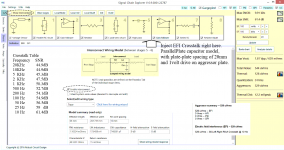
Magnetic and Electric field interference from a 3cm*6cm Capacitor
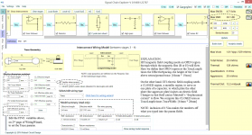
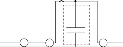
What happens when a big component requires lots of PCB area? Here we model a 3cm*6cm capacitor (30mm*60mm, 1.2inches by 2.4inches). And to emphasize a potential problem, we install this (non-polarized) capacitor backwards, with the outside foil tied to the signal, whereas in this Low Pass Filter application we could tie the outside foil to GND. We did not. See Attachment #2 for hints on the big cap position (consider this a top view).
Despite the 8 stages of this Salas-done-in-SCE, we only activate interstage connections between stage 3 and 4, where the big cap resides. See Attachment #1.
Aggressors (the interferers)? Two new aggressors [ shown in Attachment #3], both being "crosstalk" between the Left and Right channels. The EFI crosstalk is Output DC_blocker electric-flux-linked to our reverse-installed LowPassFilter cap. The HFI crosstalk is the output/load current of 62uA, coupling --- by magnetic field --- to our reverse-installed big cap.
We also turn on the EFI 117VAC over the PCB, and the HFI current to the Audio Power Amp rectifier diodes surging at peak of 60Hz waveform.
Results? With all 4 aggressors on [Gargoyles, HFI, EFI, I/C], SNR is only 30.1dB. With the EFI 117VAC off, SNR rises to 46dB. With both EFI off --- that is, the 117VAC *and* the crosstalk between the 2 capacitors, SNR rises to 73.7dB. Surprise--- seems like we just found a crosstalk problem.
And with all 4 aggressors off, we get the Johnson/Boltzmann noise limited value 74dB.
The Attachment#2 provides details of Analysis Results versus Aggressor databases.
Attachment#1 is extremely busy, because I included screen shots of page 2 of Wiring Wizard, wherein you edit the 5 variables setting TRACE params.
Attachments
Left_Right Crosstalk of DC_block caps
Realized the large output DCblocker could parasitically couple to the other channel's first DCblocker at input to 2nd NJFET. So I moved the EFI injection point to that signal chain node, as shown by big_open_arrow in Attachment. Crosstalk varies from 44.9dB SNR [such precision] at 20KHz, to 61.4dB SNR at 10Hz.
Does this crosstalk matter, if the cartridge channel-channel isolation sets the floor? probably not. On the other hand, if the crosstalk varies with frequency, will that cause the sound-stage [instrument position] to wander?
Here is the attachment.
Attachments
- Home
- Source & Line
- Analogue Source
- Simplistic NJFET RIAA