R3x is 40V. Rail stay at 50V and doesn't change with VR2X.
U
Something is bad in that channel's supply. What value is R3x? Parallel an about same value to it. Does VR2 change the rail now? If yes Q3x has high IDSS for the Rx selected, and you can use a lower value that allows good adjust range. If no change, does Q1x MOSFET show Vgs? (gate to source voltage). Q2x MOSFET does? Q4x BJT shows Vbe? (base to emitter voltage). If yes what are those figures? Is Q4x a correct BC550C and not a BC560C by mistake? Do Q3x & Q5x JFETs appear non shorted with the Ohm meter across drain and source? (when power is off). Do those checks.
Now I've sorted my grounding issues out and lowered the noise floor - this is a stunning phono. My build has fully shielded toroidal within the same case. Brilliant design.
Great

R3X was 9,1K, I put 15K in parallel and now I have 35V, Vgs are Q1X 4V, Q2x 46V, Vbe Q4X is 30V they seem ok now but I have Tp1-Tp2 0,6V.
Q3z Vbe 0,646, Q3y Vbe 0,642
Q3 Vb 7,5V, Q3 Vgd 16,1V, Q3 Ve 8,22V
R2 67mV
R3 93mV
Vr13 24,8V
I wasn t unable to measure Q4 Vd because the DVM started to whistle
Q3z Vbe 0,646, Q3y Vbe 0,642
Q3 Vb 7,5V, Q3 Vgd 16,1V, Q3 Ve 8,22V
R2 67mV
R3 93mV
Vr13 24,8V
I wasn t unable to measure Q4 Vd because the DVM started to whistle
Low side Vrail happened before in some builds given for different Leds than in the prototype and some other tolerances working towards lower. When its a trend on both channels it does not seem alarming for the previous bad one.
Some measurements you reported don't make sense though. Vbe Q4x 30V when it should be 0.6-0.7V. Maybe you measured across it for Vcb? Q2x Vgs 46V again weird, maybe you measured across it for Vds? (C-E, D-S are the outer pins in both cases). Else Q4X maybe damaged. Q2x should be alright when you got PSU LEDS on and normally bright. Also why you mention Q3z and Q3y? There should be only one Q3 BJT not two. Either BC560C in Q3y position or 2SA970BL in Q3z position. Its a choice not a two types together thing. R2 mV drop should be closer to R3 drop unless they are different or Q1 Q2 IDSS differ enough. Whistling DVM is also weird. Try measure the same things on the originally good channel and compare.
Some measurements you reported don't make sense though. Vbe Q4x 30V when it should be 0.6-0.7V. Maybe you measured across it for Vcb? Q2x Vgs 46V again weird, maybe you measured across it for Vds? (C-E, D-S are the outer pins in both cases). Else Q4X maybe damaged. Q2x should be alright when you got PSU LEDS on and normally bright. Also why you mention Q3z and Q3y? There should be only one Q3 BJT not two. Either BC560C in Q3y position or 2SA970BL in Q3z position. Its a choice not a two types together thing. R2 mV drop should be closer to R3 drop unless they are different or Q1 Q2 IDSS differ enough. Whistling DVM is also weird. Try measure the same things on the originally good channel and compare.
The remeasured Q4x Vbe you report are normal. Q2x may have different parameters but voltage drop across each R6x divided by its Ohmic value should better show the current through D2,D3,D4x Leds. Given R2 R3 are all correctly the same in value then that 66mV R2 points to a weaker Q1 connected to it. If 10 Ohm then 6.6mA instead of 9.2mA (I=V/R ). That would give 7.5% less combined transconductance than in the other channel's input stage. Maybe not noticeable. But for doing things to best of attendance replace that R2 with 7.5R and see that the new mv drop indicates correctly about 9mA now. Its matching bias currents again but via resistors.
I have reduced R2 to 4R and now I have 32,4mV thai it give 8,1mA in the others source resistors, being 10,4R, I have 8,9mA, is it a matter if I go further down with R2? I will go down with others resistors to achieve the 9,2mA target too.
Side effect of reducing R2 is the Vrail went to 32,9V that almost match the 32,4V in the other channel, that is good.
Voltage drop across R6X is 66mV the good channel has 99mV.
Side effect of reducing R2 is the Vrail went to 32,9V that almost match the 32,4V in the other channel, that is good.
Voltage drop across R6X is 66mV the good channel has 99mV.
9mA is the rough target mentioned in the guide. I don't think you should spend more time in fine tuning the input stage mA because by the now achieved closeness they make no real differences in total transconductance between the channels. Its what counts for balanced gain control. If those R6x are 33 Ohm then its 2mA and 3mA through the PSU LEDS because those Q2x differ in IDSS. Its of no interest to match, we just want low current through each Q2x to protect it from high dissipation because it carries a large voltage across its drain and source. 2mA is nicely conservative, 3mA is acceptable, just see to have no more for good long term reliability of Q2x.
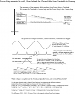
Power Strip induces 20microVolts into TwinLead, 1uV into TwistedPair
Looking at PCBs, there are loops everywhere. And wiring/cables are loops.
When you make your own twistedpair, the irregular twisting will cause inconsistent nulling of external fields. And where any cable is soldered to a connector, there will be a vulnerable loop formed by Signal & Return.
Having simple math for planar aggressor_wire and victim_loop, I use it.
I assume a PowerStrip attached to wall, 10cm behind the Audio Rack and extending a full meter left-to-right (yes, I know that is a huge Strip). I also have the TwinLead (not TwistedPair) running a meter from TurnTable to RIAA PreAmp, exactly parallel to the PowerStrip and 10cm away.
Result? A lonely wire, Hot or Return, of the PowerStrip induces 2,000uV.
The real PowerStrip, with Hot bus close to the Return bus, induces 20uV.
Into TwinLead.
Into TwistedPair, this should drop another 20X (26dB), else why use TP.
The loop area of the TwinLead is 1meter * 1mm, or 1cm*10cm, with 20uV induced.
If your construction has 1cm*1cm loops, that Power Strip will, worst case,
induce 2uV.
Here is the attachment. Avoid nearby PowerStrips.
Attachments
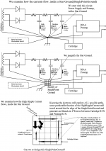
Convert Star Ground (SinglePointGround) into Distributed Ground
Respecting the need for very low noise (random and repetitive) in RIAA Preamps, I'm revisiting some thoughts on Grounds.
Any comments from the forum readers are VERY WELCOME.
With 100 milliamp DC currents and 10microOhm resistances, the voltage drops "inside" the Star are 0.1 * 10u = 1microVolt. The DC blocking inside Salas rejects this. But out of rectifier diodes, the surge currents will be 1 to 10 amps with waveform an ugly narrow-in-time broadband-in-frequency 120Hz hump.
What is to be done?
In attachment#1, I magnify the Star Ground into a 5*5 grid, with High Ripple Currents entering and exiting on the left side. I show how a fraction of that current flows between the Preamp RTN and the Cartridge RTN.
My crude FEM Finite Element Model uses Count_the_Squares analysis to predict the voltage drop between Preamp RTN and Cartridge RTN.
Observation: a large distance between High Ripple Currents and the path between Preamp/Cartridge seems a good idea. Can we do that?
In attachment#2, I stretch out the Star to bring a large distance into the grid. And I greatly narrow the middle portion of the grid, into dogbone shape.
To my surprise, again using FEM thoughts, the attenuation of the middle is approximately computable. Attenuation is 10:1 per square (2*2 elements in this square). A 1 meter wire, 2mm GND wire diameter, has 500 squares.
We expect 10^500 isolation. (Magnetic fields are another issue.)
Conclusion: we have a (approximate, using FEM) huge isolation of Ripple Currents, if we locate PowerSupply away from Preamp.
Again, comments from Forum readers are very welcome.
Attachments
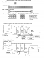
I slowly came to the conclusion that each current loop needs to be resolved locally using the lowest loop area to minimise emi.
Then connect these loops together where required.
Using your first diagram. That means the charging loop into the first capacitor should be done as a local loop, but for three wires since you have two rectifier outputs.
The second loop is the charging circuit for the second capacitor. That connects from the previous capacitor pins. This too is resolved locally using minimised loop area.
This is repeated for the third capacitor by connecting to the pins of the second capacitor. Comparing those first three loops, I can see a similarity to your second diagram. Just stretch your first 5x5 grid to a 3wide by 10long grid. The first cap -ve connects to the middle square at extreme left, the second cap -ve connects to the middle square on the 10th row. And you move the -ve route to beside or over the +ve current route.
The RIAA pre gets it's power via a low loop area two, or three wire (if dual polarity), connection from it's power source.
It is the use of low loop area connections that minimises the loop impedance, just reducing resistance does not achieve this lowest impedance requirement. Ground and power planes also achieve lowest loop area by minimising loop area. The planes allow the currents to flow in regions of the planes that lie one above the other to minimise loop area and thus minimise impedance and thus minimise emi.
I disagree with the transformer shield going to the Audio/Power Ground plane.
The shield must go to the enclosure using the lowest impedance (very short) connection. This allows the very high frequencies to couple to "Earth" via the capacitance between the enclosure and "Earth"
H.Ott discusses this. He reminds us that the very high frequencies do not return to "Earth" via the protective earth wire. That wire has far too high an impedance.
He also discusses the advantage of using wide and thin tape/strap for interconncting when lowest impedance is required. But no transformer I have ever seen has a tape shield connection. They all use a stranded (bundled) wire and make it far too long. This excessive length tempts many Builders into the trap of taking the shield via a higher impedance to some remote connection that is often not part of the enclosure.
Last edited:
I don't think those frequencies will couple to earth significantly from the capacitance of the enclosure to air. I think the reason was that immediate decoupling to chassis allowed the Faraday cage effect to take over where it works best - frequencies where skin effect matters more than almost anything else. If the UHF passes to it's destination through the "skin" of the chassis, then the internal circuitry is shielded best.
I have finished the FSP few days ago and I am very happy. Great piece of equipment in my audio room. It plays with Technics SL1200ML2 with Ortofon 2M Blue.
The preamp started from the first time, no problems. All work as it should. The voltage is +34,22V/+34,15V (from two separate toroids I have 51,00V and 51,40V). TP1 to TP2 after 30 min, 60 min and 2 hours with closed cover shows 3,584V in both channels. TP1/GND is 7,64V/7,64V and TP2/GND is 4,02 in both channels.
All resistors are Vishay 0,1-0,5% with 25-50ppm, R1 and R14 are Vishay VAR Z-Naked 47K.
Thanks Salas for another great rig!
I have finished the FSP few days ago and I am very happy. Great piece of equipment in my audio room. It plays with Technics SL1200ML2 with Ortofon 2M Blue.
The preamp started from the first time, no problems. All work as it should. The voltage is +34,22V/+34,15V (from two separate toroids I have 51,00V and 51,40V). TP1 to TP2 after 30 min, 60 min and 2 hours with closed cover shows 3,584V in both channels. TP1/GND is 7,64V/7,64V and TP2/GND is 4,02 in both channels.
All resistors are Vishay 0,1-0,5% with 25-50ppm, R1 and R14 are Vishay VAR Z-Naked 47K.
Thanks Salas for another great rig!
Your build measures by the book. Congratulations
What makes the rest of your system? Is there a picture of your build to post?Your build measures by the book. Congratulations
Thanks
") The rest of the system is Aikido Headphone Amplifier with two SSHV2 and 6CG7 Sylvania + 6H30P-DR. The headphones is moded Beyerdynamic T90.
The rest of the system is Aikido Headphone Amplifier with two SSHV2 and 6CG7 Sylvania + 6H30P-DR. The headphones is moded Beyerdynamic T90.The pictures will take and send tomorrow. Today is too late for me as I should go sleep
- Home
- Source & Line
- Analogue Source
- Simplistic NJFET RIAA