So I eventually decided to go with separate boxes for the preamp and phono stage to make it more modular in the future should I want to try different ones.
I am almost finished with wiring the FSP in the final boxes, waiting for the panels to get done in Germany. Listening without back panels the background hum is almost silent, I will have however to run an extra wire from the left RCA ground to the central ground lug as my Rega turntable doesn't have a ground wire, it is done via the left channel ground. There is some noise present, but most likely from the headphone amp I'm using as provisory preamp.
I do however have so noise coming from the turntable PSU, and I can hear the motor turning on the speakers, sort of a metal scratching on glass noise, very low level but it is there.
I will report back when I have the panels installed and play around with positioning and connections.
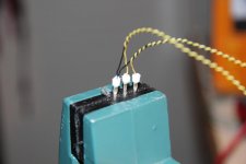
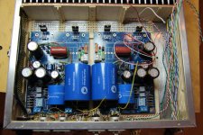
Halfway though backpaneling. I use very thin solid signalcabling so I clamp them in the ends so I dont kill them everytime I test install them. PCB relays was a little tricky to solder but I hope it will work in the long run. Works now anyway.
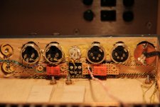
Todo is FSP in, 4 pole XLR Line 1 and 2 in. Left relay is output select between leftest 4 pole XLR and the two RCA, soldered to XLR as NC. Rightest relay is select between FSP direct out (NC) and FSP to Muses Electronic volume control.
That meens after soldering FSP in from the female 5 pole DIN in the middle (2 ch plus ground lug), mounting the boards, convering a vinyl rig to DIN, and rig a temporary PSU I could play some records if I get starved")
Now off to some boatjob, update in the evening.
Todo is FSP in, 4 pole XLR Line 1 and 2 in. Left relay is output select between leftest 4 pole XLR and the two RCA, soldered to XLR as NC. Rightest relay is select between FSP direct out (NC) and FSP to Muses Electronic volume control.
That meens after soldering FSP in from the female 5 pole DIN in the middle (2 ch plus ground lug), mounting the boards, convering a vinyl rig to DIN, and rig a temporary PSU I could play some records if I get starved
Now off to some boatjob, update in the evening.
Attachments
I finished PSU wiring with proper grounding and also proper grounding in the phono box.
I still get the slightest noise with volume at max, but the case still doesn't have the back panel. It is however unnoticeable at normal listening levels. I am listening to much more detail and resolution in the sound. It is sounding very good already!!
I fixed the TT power supply noise by running a wire connecting the phono psu and turntable psu boxes. It went completely away.
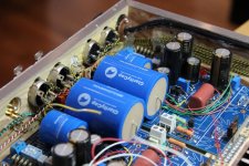
Some progress after a coup interruption. I did arrange the interior signal cabling a bit, tried the FSP boards and found that i had mounted the right relay straight into FSP out sockets, grr, but dremel and superglue is my friends so I moved the relay a bit and dremeled a mm on that FSP board to squeeze it in. Its getting really crowded so it was time to test the signal ways.
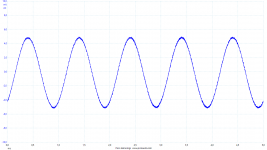
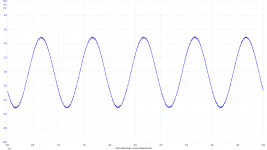
Firstly I went over it with DMM Buzz and made sure there was contact where it should, and it was. Then I wanted to look for eventual interferences so I rigged the scope and signal generator. A tiny 5 mV RMS sinus signal was sent thru each and every signal way, switching the relays to see that it worked and donesnt pick up interference from relay coils or other stuff. Showing a pic on scope to gen direct and then a general picture on the same with a signal way inbetween, this one is DCB1 out thru activated relay to XLR female. All of them looked pretty much the same. Interference is background noice cause it so small signal and no top plate on box.
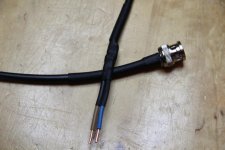
For the female XLRs I had to make an adaptor cause it was to crowded to mount any probe or clip anywhere. Made it from RG45 and solid 1,5 mm copper wires to stick into the XLR holes. Worked great.
Time to mount boards and further interconnects, then power.
Firstly I went over it with DMM Buzz and made sure there was contact where it should, and it was. Then I wanted to look for eventual interferences so I rigged the scope and signal generator. A tiny 5 mV RMS sinus signal was sent thru each and every signal way, switching the relays to see that it worked and donesnt pick up interference from relay coils or other stuff. Showing a pic on scope to gen direct and then a general picture on the same with a signal way inbetween, this one is DCB1 out thru activated relay to XLR female. All of them looked pretty much the same. Interference is background noice cause it so small signal and no top plate on box.
For the female XLRs I had to make an adaptor cause it was to crowded to mount any probe or clip anywhere. Made it from RG45 and solid 1,5 mm copper wires to stick into the XLR holes. Worked great.
Time to mount boards and further interconnects, then power.
Attachments
The relay coil operates on DC with a bit of noise.
The DC current cannot create emi. It needs a changing current to do that.
The interference/noise mixed with the DC is a changing current and can emit emi. We attenuate that by keeping the noise/interference level on the DC feed as low as reasonable and by sending the flow and return currents along a close coupled, or twisted pair.
The combination of low noise and close coupling turns the interference into a non problem for line level signals.
Compare the AC heater current in a valve and what it does to interfere with the wanted signal. Here the interference current could be nearly a million times (+120dB) higher and yet I believe they only do noise/hum attenuation for low signal level stages.
I replaced q1&2, q4,5,6 on both channels with matched sets from tea bag. Both channels work and sound about the same in the workroom audio system. I'll try it out on the main system later.
Before that, bias in the previously bad channel is close to limits: tp1-2 = 3.88 with rail at 37.3; other channel is 3.85 at 35.6.
Any concerns?
Thanks
Before that, bias in the previously bad channel is close to limits: tp1-2 = 3.88 with rail at 37.3; other channel is 3.85 at 35.6.
Any concerns?
Thanks
I replaced q1&2, q4,5,6 on both channels with matched sets from tea bag. Both channels work and sound about the same in the workroom audio system. I'll try it out on the main system later.
Before that, bias in the previously bad channel is close to limits: tp1-2 = 3.88 with rail at 37.3; other channel is 3.85 at 35.6.
Any concerns?
Thanks
No real concerns. Still you can try with VR1s to go TP1-2=3.6V
No real concerns. Still you can try with VR1s to go TP1-2=3.6V
OK. I'll set both channels at 3.6, but the rail voltage, on one side, will increase above 37.3.
Then it is easy to add an RC stage into the power supply.OK. I'll set both channels at 3.6, but the rail voltage, on one side, will increase above 37.3.
The C provides the small change in current when an AC signal is being processed.
The R drops some voltage and this is nearly constant because the main load is DC with very little AC content.
Alright Barry, you will have averagely compatible idss with most buidls here at least. Check what R2 R3 resistors from the guide again when you will know what idss Mike will send.
Thanks to Teabag the SK369s have made there way to me safely and are now fitted in the PCBs together with the recommended R1 and R2. No problems setting the bias up now.
initial impressions are very good. Will let it settle before making any changes.
Photos to follow soon.
Barry

The inside
As you can see I cut back the PCB to allow the four power devices to heat sink against the aluminium chassis. The chassis is the pressed against gap pad and onto the heat sink. The four devices are isolated from the metalwork.
All the four devices run very cool.
The acrylic lid is not fitted.
Barry
As you can see I cut back the PCB to allow the four power devices to heat sink against the aluminium chassis. The chassis is the pressed against gap pad and onto the heat sink. The four devices are isolated from the metalwork.
All the four devices run very cool.
The acrylic lid is not fitted.
Barry
Attachments
![20160727_210118 [30061].jpg](/community/data/attachments/509/509861-e7bbcb4303a704f629d6ce43d966567e.jpg)
![20160727_210048 [30125].jpg](/community/data/attachments/509/509878-4dcc555211111e569759fa3b9576e765.jpg)
- Home
- Source & Line
- Analogue Source
- Simplistic NJFET RIAA