I reflowed the joint and nothing changed.
I am now getting 47V between ground and rail + with no adjustment on Vr2x. I did nothing but measure voltages on the different transistors, and from different transistors to rail and ground to try to find differences between boards.
must have shorted something...
I am now getting 47V between ground and rail + with no adjustment on Vr2x. I did nothing but measure voltages on the different transistors, and from different transistors to rail and ground to try to find differences between boards.
must have shorted something...
Last edited:
They are still P-MOS enhancement mode parts with different gm and parasitic capacitances that would basically work interchanged apart from changing the expected bias currents and the frequency performance. But if an oscillation occurred due to that, it could hold the Vout back or overheat a semi.That would be bad! But it happens!")
Got the same issue check for Q4X it might be shorted.
Possible in the new problem description phase because before he reported good Vbe reading for it
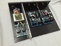
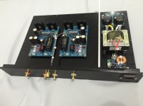
Nice sectioning and short AC cabling, nice signal cabling dressing also, but don't trust an aluminum section can stop hum field if intrusive. Mu metal or copper Gauss band shielded transformer and proper orientation are better. The distance seems good though and it *may* turn out fine. Easier to succeed when in MM or high MC mode, since its one JFET only I see in the input stage.
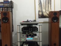
the speaker is Unity Audio CLA-1.
http://www.cerioustechnologies.com/pdf files/cla_lit.pdf
Salas this is my first Phono preamp, please bear with me if I will bother you sometimes.
http://www.cerioustechnologies.com/pdf files/cla_lit.pdf
Salas this is my first Phono preamp, please bear with me if I will bother you sometimes.
Will wrap the trafo with copper sheet.
Try it as it is first since MM gain is not too sensitive for hum pick up
- Home
- Source & Line
- Analogue Source
- Simplistic NJFET RIAA